
Chapter 17: Electrochemistry
17.5 Batteries and Fuel Cells
Learning Outcomes
- Describe the electrochemistry associated with several common batteries
- Distinguish the operation of a fuel cell from that of a battery
There are many technological products associated with the past two centuries of electrochemistry research, none more immediately obvious than the battery. A battery is a galvanic cell that has been specially designed and constructed in a way that best suits its intended use a source of electrical power for specific applications. Among the first successful batteries was the Daniell cell, which relied on the spontaneous oxidation of zinc by copper(II) ions (Figure 17.5.1):
[latex]\ce{Zn} (s) + \ce{Cu^2+} (aq) \longrightarrow \ce{Zn^2+} (aq) + \ce{Cu} (s)[/latex]
Modern batteries exist in a multitude of forms to accommodate various applications, from tiny button batteries that provide the modest power needs of a wristwatch to the very large batteries used to supply backup energy to municipal power grids. Some batteries are designed for single-use applications and cannot be recharged (primary cells), while others are based on conveniently reversible cell reactions that allow recharging by an external power source (secondary cells). This section will provide a summary of the basic electrochemical aspects of several batteries familiar to most consumers, and will introduce a related electrochemical device called a fuel cell that can offer improved performance in certain applications.
Single Use Batteries
A common primary battery is the dry cell, which uses a zinc can as both container and anode (“[latex]–[/latex]” terminal) and a graphite rod as the cathode (“+” terminal). The Zn can is filled with an electrolyte paste containing manganese(IV) oxide, zinc(II) chloride, ammonium chloride, and water. A graphite rod is immersed in the electrolyte paste to complete the cell. The spontaneous cell reaction involves the oxidation of zinc:
[latex]\text{anode reaction:} \,\,\,\,\, \ce{Zn} (s) \longrightarrow \ce{Zn^2+} (aq) + \ce{e-}[/latex]
and the reduction of manganese(IV)
[latex]\text{reduction reaction:} \,\,\,\,\, \ce{2MnO2} (s) + \ce{2NH4Cl} (aq) + \ce{2e-} \longrightarrow \ce{Mn2O3} (s) + \ce{2NH3} (aq)+\ce{H2O} (l)+\ce{2Cl-}[/latex]
which together yield the cell reaction:
[latex]\text{cell reaction:} \,\,\,\,\, \ce{2MnO2} (s) + \ce{2NH4Cl} (aq) + \ce{Zn} (s)\longrightarrow \ce{Zn^2+} (aq) + \ce{Mn2O3} (s) + 2\text{NH}_3 (aq) + \ce{H2O} (l)+\ce{2Cl-} \,\,\,\,\, \qquad{E}_{cell}-1.5\text{V}[/latex]
The voltage (cell potential) of a dry cell is approximately 1.5 V. Dry cells are available in various sizes (e.g., D, C, AA, AAA). All sizes of dry cells comprise the same components, and so they exhibit the same voltage, but larger cells contain greater amounts of the redox reactants and therefore are capable of transferring correspondingly greater amounts of charge. Like other galvanic cells, dry cells may be connected in series to yield batteries with greater voltage outputs, if needed.
Alkaline batteries (Figure 17.5.3) were developed in the 1950s to improve on the performance of the dry cell, and they were designed around the same redox couples. As their name suggests, these types of batteries use alkaline electrolytes, often potassium hydroxide. The reactions are
[latex]\text{anode:} \,\,\,\, \ce{Zn} (s) + \ce{2OH} (aq) \longrightarrow \ce{ZnO} (s) + \ce{H2O} (l) + \ce{2e-}[/latex][latex]\text{cathode:} \,\,\,\, \ce{2MnO2} (s) + \ce{H2O} (l) + \ce{2e-} \longrightarrow \ce{Mn2O3} (s) + \ce{2OH-} (aq)[/latex]
[latex]\text{cell:} \,\,\,\, \ce{Zn} (s) + \ce{2MnO2} (s) \longrightarrow \ce{ZnO} (s) + \ce{Mn2O3} (s) \,\,\,\, \qquad{E}_\text{cell}^\circ = \text{+1.43 V}[/latex]
An alkaline battery can deliver about three to five times the energy of a zinc-carbon dry cell of similar size. Alkaline batteries are prone to leaking potassium hydroxide, so these should be removed from devices for long-term storage. While some alkaline batteries are rechargeable, most are not. Attempts to recharge an alkaline battery that is not rechargeable often leads to rupture of the battery and leakage of the potassium hydroxide electrolyte.
Rechargeable (Secondary) Batteries
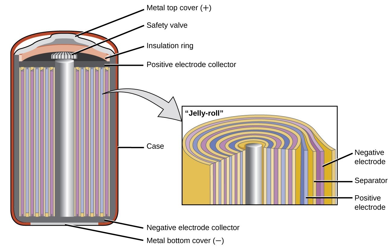
Nickel-cadmium, or [latex]\ce{NiCd}[/latex], batteries (Figure 17.5.4) consist of a nickel-plated cathode, cadmium-plated anode, and a potassium hydroxide electrode. The positive and negative plates, which are prevented from shorting by the separator, are rolled together and put into the case. This is a “jelly-roll” design and allows the NiCd cell to deliver much more current than a similar-sized alkaline battery. The reactions are
[latex]\text{anode:} \,\,\,\, \ce{Cd} (s) + \ce{2OH-} (aq) \longrightarrow \ce{Cd(OH)2} (s) + \ce{2e-}[/latex][latex]\text{cathode:} \,\,\,\, \ce{NiO2} (s) + \ce{2H2O} (l) + \ce{2e-} \longrightarrow \ce{Ni(OH)2} (s) + \ce{2OH-} (aq)[/latex]
[latex]\text{cell:} \,\,\,\, \ce{Cd} (s) + \ce{NiO2} (s) + \ce{2H2O} (l) \longrightarrow \ce{Cd(OH)2} (s) + \ce{Ni(OH)2} (s) \,\,\,\, \qquad{E}_{cell}\text{~}1.2\text{V}[/latex]
When properly treated, a NiCd battery can be recharged about 1000 times. Cadmium is a toxic heavy metal so NiCd batteries should never be ruptured or incinerated, and they should be disposed of in accordance with relevant toxic waste guidelines, never put in the regular trash.
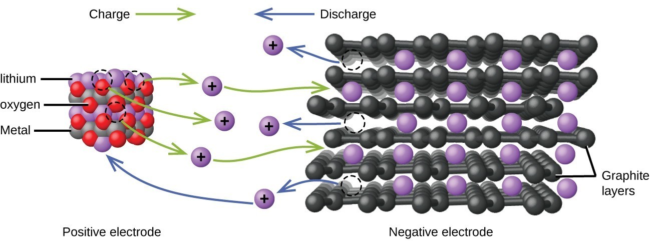
Lithium ion batteries (Figure 17.5.5) are among the most popular rechargeable batteries and are used in many portable electronic devices. The reactions are
[latex]\text{anode:} \,\,\,\, \ce{LiCoO2} \rightleftharpoons \ce{Li{1-x}}\ce{CoO2} + x\ce{Li+} + x\text{e}^-[/latex][latex]\text{cathode:} \,\,\,\, x\ce{Li+} + x\text{e-} + x\ce{C6} \rightleftharpoons x\ce{LiC6}[/latex]
[latex]\text{cell:} \,\,\,\, \ce{LiCoO2} +x\ce{C6} \rightleftharpoons \ce{Li{1-x}}\ce{CoO2} + x\ce{LiC6} \,\,\,\, \qquad{E}_{cell}\text{~}3.7\text{V}[/latex]
The variable stoichiometry of the cell reaction leads to variation in cell voltages, but for typical conditions, x is usually no more than 0.5 and the cell voltage is approximately 3.7 V. Lithium batteries are popular because they can provide a large amount current, are lighter than comparable batteries of other types, produce a nearly constant voltage as they discharge, and only slowly lose their charge when stored.
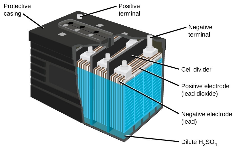
The lead acid battery (Figure 17.5.6) is the type of secondary battery used in your automobile. It is inexpensive and capable of producing the high current required by automobile starter motors. The reactions for a lead acid battery are
[latex]\text{anode:} \,\,\,\, \ce{Pb} (s) + \ce{HSO4-} (aq) \longrightarrow \ce{PbSO4} (s) + \ce{H+} (aq) + \ce{2e-}[/latex][latex]\text{cathode:} \,\,\,\, \ce{PbO2} (s) + \ce{HSO4-} (aq) + \ce{3H+} (aq) + \ce{2e-} \longrightarrow \ce{PbSO4} (s) + \ce{2H2O} (l)[/latex]
[latex]\text{cell:} \,\,\,\, \ce{Pb} (s) + \ce{PbO2} (s) + \ce{2H2SO4} (aq) \longrightarrow \ce{2PbSO4} (s) + \ce{2H2O} (l) \,\,\,\, \qquad{E}_{cell}\text{~}2\text{V}[/latex]
Each cell produces 2 V, so six cells are connected in series to produce a 12-V car battery. Lead acid batteries are heavy and contain a caustic liquid electrolyte, but are often still the battery of choice because of their high current density. Since these batteries contain a significant amount of lead, they must always be disposed of properly.
Fuel Cells
A fuel cell is a galvanic cell that uses traditional combustive fuels, most often hydrogen or methane, that are continuously fed into the cell along with an oxidant. (An alternative, but not very popular, name for a fuel cell is a flow battery.) Within the cell, fuel and oxidant undergo the same redox chemistry as when they are combusted, but via a catalyzed electrochemical that is significantly more efficient. For example, a typical hydrogen fuel cell uses graphite electrodes embedded with platinum-based catalysts to accelerate the two half-cell reactions:
In a hydrogen fuel cell, the reactions are
[latex]\text{anode:} \,\,\,\, \ce{2H2} (g) \longrightarrow \ce{4H+} (aq) + \ce{4e-}[/latex][latex]\text{cathode:} \,\,\,\, \ce{O2} (g) + \ce{4H+} (aq) + \text{4e}^- \longrightarrow \ce{2H2O} (g)[/latex]
[latex]\text{cell:} \,\,\,\, \ce{2H2} (g) + \ce{O2} (g) \longrightarrow \ce{2H2O} (g) \,\,\,\, \qquad{E}_{cell}\text{~}1.2\text{V}[/latex]
These types of fuel cells generally produce voltages of approximately 1.2 V. Compared to an internal combustion engine, the energy efficiency of a fuel cell using the same redox reaction is typically more than double (~20%–25% for an engine versus ~50%–75% for a fuel cell). Hydrogen fuel cells are commonly used on extended space missions, and prototypes for personal vehicles have been developed, though the technology remains relatively immature.
Key Concepts and Summary
Galvanic cells designed specifically to function as electrical power supplies are called batteries. A variety of both single-use batteries (primary cells) and rechargeable batteries (secondary cells) are commercially available to serve a variety of applications, with important specifications including voltage, size, and lifetime. Fuel cells, sometimes called flow batteries, are devices that harness the energy of spontaneous redox reactions normally associated with combustion processes. Like batteries, fuel cells enable the reaction’s electron transfer via an external circuit, but they require continuous input of the redox reactants (fuel and oxidant) from an external reservoir. Fuel cells are typically much more efficient in converting the energy released by the reaction to useful work in comparison to internal combustion engines
Try It
- What are the desirable qualities of an electric battery?
- List some things that are typically considered when selecting a battery for a new application.
- Consider a battery made from one half-cell that consists of a copper electrode in 1 M [latex]\ce{CuSO4}[/latex] solution and another half-cell that consists of a lead electrode in 1 M [latex]\ce{Pb(NO3)2}[/latex] solution.
- What are the reactions at the anode, cathode, and the overall reaction?
- What is the standard cell potential for the battery?
- Most devices designed to use dry-cell batteries can operate between 1.0 and 1.5 V. Could this cell be used to make a battery that could replace a dry-cell battery? Why or why not.
- Suppose sulfuric acid is added to the half-cell with the lead electrode and some [latex]\ce{PbSO4}[/latex](s) forms. Would the cell potential increase, decrease, or remain the same?
- Consider a battery with the overall reaction: [latex]\ce{Cu}(s)+\ce{2Ag+}(aq)\longrightarrow \ce{2Ag}(s)+\ce{Cu^2+}(aq)[/latex].
- What is the reaction at the anode and cathode?
- A battery is “dead” when it has no cell potential. What is the value of Q when this battery is dead?
- If a particular dead battery was found to have [latex]\ce{[Cu^2+]}[/latex] = 0.11 M, what was the concentration of silver ion?
- An inventor proposes using a SHE (standard hydrogen electrode) in a new battery for smartphones that also removes toxic carbon monoxide from the air:
[latex]\begin{array}{rll}\text{Anode:}&\ce{CO}\left(g\right)+{\ce{H}}_{2}\ce{O}\left(l\right)\longrightarrow {\ce{CO}}_{2}\left(g\right)+{\ce{2H}}^{\text{+}}\left(aq\right)+{\text{2e}}^{-}&{E}_{\text{anode}}^{\circ }=-\text{0.53 V}\\ \text{Cathode:}&2{\text{H}}^{\text{+}}\left(aq\right)+{\text{2e}}^{-}\longrightarrow {\ce{H}}_{2}\left(g\right)&{E}_{\text{cathode}}^{\circ }=\text{0 V}\\ \\ \text{Overall:}&\ce{CO}\left(g\right)+{\ce{H}}_{2}\ce{O}\left(l\right)\longrightarrow {\ce{CO}}_{2}\left(g\right)+{\ce{H}}_{2}\left(g\right)&{E}_{\text{cell}}^{\circ }=\text{+0.53 V}\end{array}[/latex]
Would this make a good battery for smartphones? Why or why not? - Why do batteries go dead, but fuel cells do not?
- Explain what happens to battery voltage as a battery is used, in terms of the Nernst equation.
- Using the information thus far in this chapter, explain why battery-powered electronics perform poorly in low temperatures.
Show Solution
- Considerations include: cost of the materials used in the battery, toxicity of the various components (what constitutes proper disposal), should it be a primary or secondary battery, energy requirements (the “size” of the battery/how long should it last), will a particular battery leak when the new device is used according to directions, and its mass (the total mass of the new device).
- The answers are as follows:
- The reactions are:
[latex]\begin{array}{rll}\text{anode: Cu}&\left(s\right)\longrightarrow {\ce{Cu}}^{2+}\left(aq\right)+{\text{2e}}^{-}&{E}_{\text{anode}}^{\circ }=\text{0.34 V}\\ \text{cathode:}&2\times \left({\text{Ag}}^{\text{+}}\left(aq\right)+{\text{e}}^{-}\longrightarrow \ce{Ag}\left(s\right)\right)&{E}_{\text{cathode}}^{\circ }=\text{0.7996 V}\\ \\ \text{overall: Cu}&\left(s\right)+{\ce{2Ag}}^{\text{+}}\left(aq\right)\rightleftharpoons {\ce{Cu}}^{2+}\left(aq\right)+\ce{2Ag}\left(s\right)&{E}_{\text{cell}}^{\circ }=\text{0.46 V}\end{array}[/latex] - Using the Nernst equation with n = 2:
[latex]{E}_{\text{cell}}={E}_{\text{cell}}^{\circ }-\frac{\text{0.0592 V}}{n}\text{log}Q[/latex]
[latex]0=\text{0.46 V}-\frac{\text{0.0592 V}}{2}\text{log}Q\,\,\,\,\,\,\,\text{or}\,\,\,\,\,\,\,Q={10}^{2\times \text{0.46 V}\text{/}\text{0.0592 V}}={10}^{15.54}=3.5\times {10}^{15}[/latex] - Using the value of Q just calculated:
[latex]Q=3.5\times{10}^{15}=\frac{\left[\ce{Cu}^{2+}\right]}{\left[\ce{Ag}^{+}\right]^{2}}\,\,\,\,\,\,\,\text{or}\,\,\,\,\,\,\,\left[\ce{Ag}^{+}\right]=\sqrt{\frac{\left[\ce{Cu}^{2+}\right]}{3.5\times{10}^{15}}}=5.6\times{10}^{-9}M[/latex]
- The reactions are:
- Batteries are self-contained and have a limited supply of reagents to expend before going dead. Alternatively, battery reaction byproducts accumulate and interfere with the reaction. Because a fuel cell is constantly resupplied with reactants and products are expelled, it can continue to function as long as reagents are supplied.
- Ecell, as described in the Nernst equation, has a term that is directly proportional to temperature. At low temperatures, this term is decreased, resulting in a lower cell voltage provided by the battery to the device—the same effect as a battery running dead.
Glossary
alkaline battery: primary battery that uses an alkaline (often potassium hydroxide) electrolyte; designed to be an exact replacement for the dry cell, but with more energy storage and less electrolyte leakage than typical dry cell
battery: galvanic cell or series of cells that produces a current; in theory, any galvanic cell
dry cell: primary battery, also called a zinc-carbon battery; can be used in any orientation because it uses a paste as the electrolyte; tends to leak electrolyte when stored
fuel cell: devices that produce an electrical current as long as fuel and oxidizer are continuously added; more efficient than internal combustion engines
lead acid battery: secondary battery that consists of multiple cells; the lead acid battery found in automobiles has six cells and a voltage of 12 V
lithium ion battery: very popular secondary battery; uses lithium ions to conduct current and is light, rechargeable, and produces a nearly constant potential as it discharges
nickel-cadmium battery: (NiCd battery) secondary battery that uses cadmium, which is a toxic heavy metal; heavier than lithium ion batteries, but with similar performance characteristics
primary battery: single-use nonrechargeable battery
secondary battery: battery that can be recharged
Licenses and Attributions (Click to expand)
CC licensed content, Shared previously
- Chemistry 2e. Provided by: OpenStax. Located at: https://openstax.org/. License: CC BY: Attribution. License Terms: Access for free at
https://openstax.org/books/chemistry-2e/pages/1-introduction
All rights reserved content
- Dry Cell – Definition, Working Principle, History, Parts of Dry Cell, Chemical reactions. Authored by: TutorVista. Located at: https://youtu.be/UEPJXSXw7HA. License: Other. License Terms: Standard YouTube License
- Single-use cells & batteries. Authored by: Rees Films. Located at: https://youtu.be/EpCGAgLbKwc. License: Other. License Terms: Standard YouTube License
- Lithium-ion batteries: How do they work?. Authored by: BASF. Located at: https://youtu.be/2PjyJhe7Q1g. License: Other. License Terms: Standard YouTube License
- How a lead-acid battery works. Authored by: engineerguy. Located at: https://youtu.be/rhIRD5YVNbs. License: Other. License Terms: Standard YouTube License
- How does a hydrogen fuel cell work? (AKIO TV). Authored by: AKIO TV. Located at: https://youtu.be/9zgx-PlDEKA. License: Other. License Terms: Standard YouTube License
galvanic cell or series of cells that produces a current; in theory, any galvanic cell
devices that produce an electrical current as long as fuel and oxidizer are continuously added; more efficient than internal combustion engines
single-use nonrechargeable battery
primary battery, also called a zinc-carbon battery; can be used in any orientation because it uses a paste as the electrolyte; tends to leak electrolyte when stored
primary battery that uses an alkaline (often potassium hydroxide) electrolyte; designed to be an exact replacement for the dry cell, but with more energy storage and less electrolyte leakage than typical dry cell
(NiCd battery) secondary battery that uses cadmium, which is a toxic heavy metal; heavier than lithium ion batteries, but with similar performance characteristics
very popular secondary battery; uses lithium ions to conduct current and is light, rechargeable, and produces a nearly constant potential as it discharges
secondary battery that consists of multiple cells; the lead acid battery found in automobiles has six cells and a voltage of 12 V
battery that can be recharged
devices that produce an electrical current as long as fuel and oxidizer are continuously added; more efficient than internal combustion engines
