
Chapter 13. Electromagnetic Induction
13.4 Induced Electric Fields
Learning Objectives
By the end of this section, you will be able to:
- Connect the relationship between an induced emf from Faraday’s law to an electric field, thereby showing that a changing magnetic flux creates an electric field
- Solve for the electric field based on a changing magnetic flux in time
The fact that emfs are induced in circuits implies that work is being done on the conduction electrons in the wires. What can possibly be the source of this work? We know that it’s neither a battery nor a magnetic field, for a battery does not have to be present in a circuit where current is induced, and magnetic fields never do work on moving charges. The answer is that the source of the work is an electric field [latex]\stackrel{\to }{\textbf{E}}[/latex] that is induced in the wires. The work done by [latex]\stackrel{\to }{\textbf{E}}[/latex] in moving a unit charge completely around a circuit is the induced emf ε; that is,
where [latex]\oint[/latex] represents the line integral around the circuit. Faraday’s law can be written in terms of the induced electric field as
There is an important distinction between the electric field induced by a changing magnetic field and the electrostatic field produced by a fixed charge distribution. Specifically, the induced electric field is nonconservative because it does net work in moving a charge over a closed path, whereas the electrostatic field is conservative and does no net work over a closed path. Hence, electric potential can be associated with the electrostatic field, but not with the induced field. The following equations represent the distinction between the two types of electric field:
Our results can be summarized by combining these equations:
Example
Induced Electric Field in a Circular Coil
What is the induced electric field in the circular coil of Example 13.2 (and Figure 13.9) at the three times indicated?
Strategy
Using cylindrical symmetry, the electric field integral simplifies into the electric field times the circumference of a circle. Since we already know the induced emf, we can connect these two expressions by Faraday’s law to solve for the induced electric field.
Solution
Show Answer
The induced electric field in the coil is constant in magnitude over the cylindrical surface, similar to how Ampere’s law problems with cylinders are solved. Since [latex]\stackrel{\to }{\textbf{E}}[/latex] is tangent to the coil,
When combined with Equation 13.12, this gives
The direction of [latex]\epsilon[/latex] is counterclockwise, and [latex]\stackrel{\to }{\textbf{E}}[/latex] circulates in the same direction around the coil. The values of E are
Significance
When the magnetic flux through a circuit changes, a nonconservative electric field is induced, which drives current through the circuit. But what happens if [latex]dB\text{/}dt\ne 0[/latex] in free space where there isn’t a conducting path? The answer is that this case can be treated as if a conducting path were present; that is, nonconservative electric fields are induced wherever [latex]dB\text{/}dt\ne 0,[/latex] whether or not there is a conducting path present.
These nonconservative electric fields always satisfy Equation 13.12. For example, if the circular coil of Figure 13.9 were removed, an electric field in free space at [latex]r=0.50\phantom{\rule{0.2em}{0ex}}\text{m}[/latex] would still be directed counterclockwise, and its magnitude would still be 1.9 V/m at [latex]t=0[/latex], 1.5 V/m at [latex]t=5.0\phantom{\rule{0.2em}{0ex}}×\phantom{\rule{0.2em}{0ex}}1{0}^{\text{−}2}\phantom{\rule{0.2em}{0ex}}\text{s},[/latex] etc. The existence of induced electric fields is certainly not restricted to wires in circuits.
Example
Electric Field Induced by the Changing Magnetic Field of a Solenoid
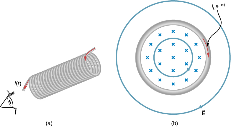
Part (a) of Figure 13.18 shows a long solenoid with radius R and n turns per unit length; its current decreases with time according to [latex]I={I}_{0}{e}^{\text{−}\alpha t}.[/latex] What is the magnitude of the induced electric field at a point a distance r from the central axis of the solenoid (a) when [latex]r>R[/latex] and (b) when [latex]r < R[/latex] [see part (b) of Figure 13.18]. (c) What is the direction of the induced field at both locations? Assume that the infinite-solenoid approximation is valid throughout the regions of interest.
Strategy
Using the formula for the magnetic field inside an infinite solenoid and Faraday’s law, we calculate the induced emf. Since we have cylindrical symmetry, the electric field integral reduces to the electric field times the circumference of the integration path. Then we solve for the electric field.
Solution
Show Answer
- The magnetic field is confined to the interior of the solenoid where
[latex]B={\mu }_{0}nI={\mu }_{0}n{I}_{0}{e}^{\text{−}\alpha t}.[/latex]
Thus, the magnetic flux through a circular path whose radius r is greater than R, the solenoid radius, is
[latex]{\text{Φ}}_{\text{m}}=BA={\mu }_{0}n{I}_{0}\pi {R}^{2}{e}^{\text{−}\alpha t}.[/latex]
The induced field [latex]\stackrel{\to }{\textbf{E}}[/latex] is tangent to this path, and because of the cylindrical symmetry of the system, its magnitude is constant on the path. Hence, we have
[latex]\begin{array}{ccc}\hfill |\oint \stackrel{\to }{\textbf{E}}·d\stackrel{\to }{\textbf{l}}|& =\hfill & |\frac{d{\text{Φ}}_{\text{m}}}{dt}|,\hfill \\ \\ \\ \hfill E\left(2\pi r\right)& =\hfill & |\frac{d}{dt}\left({\mu }_{0}n{I}_{0}\pi {R}^{2}{e}^{\text{−}\alpha t}\right)|=\alpha {\mu }_{0}n{I}_{0}\pi {R}^{2}{e}^{\text{−}\alpha t},\hfill \\ \\ \\ \hfill E& =\hfill & \frac{\alpha {\mu }_{0}n{I}_{0}{R}^{2}}{2r}{e}^{\text{−}\alpha t}\phantom{\rule{0.5em}{0ex}}\left(r>R\right).\hfill \end{array}[/latex] - For a path of radius r inside the solenoid, [latex]{\text{Φ}}_{\text{m}}=B\pi {r}^{2},[/latex] so
[latex]E\left(2\pi r\right)=|\frac{d}{dt}\left({\mu }_{0}n{I}_{0}\pi {r}^{2}{e}^{\text{−}\alpha t}\right)|=\alpha {\mu }_{0}n{I}_{0}\pi {r}^{2}{e}^{\text{−}\alpha t},[/latex]
and the induced field is
[latex]E=\frac{\alpha {\mu }_{0}n{I}_{0}r}{2}{e}^{\text{−}\alpha t}\phantom{\rule{0.2em}{0ex}}\left(r < R\right).[/latex] - The magnetic field points into the page as shown in part (b) and is decreasing. If either of the circular paths were occupied by conducting rings, the currents induced in them would circulate as shown, in conformity with Lenz’s law. The induced electric field must be so directed as well.
Significance
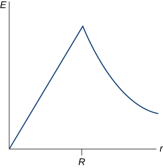
In part (b), note that [latex]|\stackrel{\to }{\textbf{E}}|[/latex] increases with r inside and decreases as 1/r outside the solenoid, as shown in Figure 13.19.
Check Your Understanding
Suppose that the coil of Example 13.2 is a square rather than circular. Can Equation 13.12 be used to calculate (a) the induced emf and (b) the induced electric field?
Show Solution
a. yes; b. Yes; however there is a lack of symmetry between the electric field and coil, making [latex]\oint \stackrel{\to }{\textbf{E}}·d\stackrel{\to }{\textbf{l}}[/latex] a more complicated relationship that can’t be simplified as shown in the example.
Check Your Understanding
What is the magnitude of the induced electric field in Example 13.8 at [latex]t=0[/latex] if [latex]r=6.0\phantom{\rule{0.2em}{0ex}}\text{cm},[/latex] [latex]R=2.0\phantom{\rule{0.2em}{0ex}}\text{cm},n=2000[/latex] turns per meter, [latex]{I}_{0}=2.0\phantom{\rule{0.2em}{0ex}}\text{A},[/latex] and [latex]\alpha =200\phantom{\rule{0.2em}{0ex}}{\text{s}}^{\text{−}1}?[/latex]
Show Solution
[latex]3.4\phantom{\rule{0.2em}{0ex}}×\phantom{\rule{0.2em}{0ex}}{10}^{-3}\phantom{\rule{0.2em}{0ex}}\text{V}\text{/}\text{m}[/latex]
Check Your Understanding
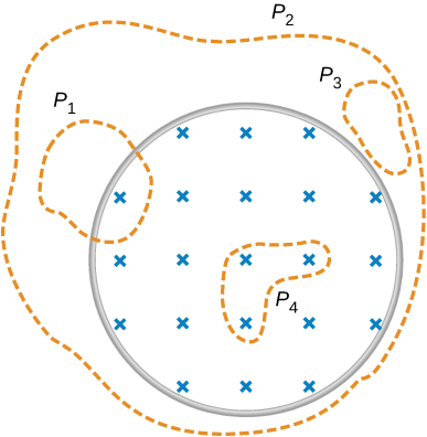
The magnetic field shown below is confined to the cylindrical region shown and is changing with time. Identify those paths for which [latex]\epsilon =\oint \stackrel{\to }{\textbf{E}}·d\stackrel{\to }{\textbf{l}}\ne 0.[/latex]
Show Solution
[latex]{P}_{1},{P}_{2},{P}_{4}[/latex]
Check Your Understanding
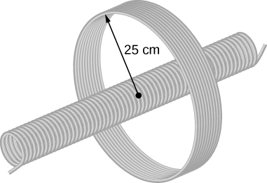
A long solenoid of cross-sectional area [latex]5.0\phantom{\rule{0.2em}{0ex}}{\text{cm}}^{2}[/latex] is wound with 25 turns of wire per centimeter. It is placed in the middle of a closely wrapped coil of 10 turns and radius 25 cm, as shown below. (a) What is the emf induced in the coil when the current through the solenoid is decreasing at a rate [latex]dI\text{/}dt=-0.20\phantom{\rule{0.2em}{0ex}}\text{A}\text{/}\text{s}?[/latex] (b) What is the electric field induced in the coil?
Show Solution
a. [latex]3.1\phantom{\rule{0.2em}{0ex}}×\phantom{\rule{0.2em}{0ex}}1{0}^{\text{−}6}\text{V};[/latex] b. [latex]2.0\phantom{\rule{0.2em}{0ex}}×\phantom{\rule{0.2em}{0ex}}{10}^{\text{−}7}\phantom{\rule{0.2em}{0ex}}\text{V}\text{/}\text{m}[/latex]
Summary
- A changing magnetic flux induces an electric field.
- Both the changing magnetic flux and the induced electric field are related to the induced emf from Faraday’s law.
Conceptual Questions
Is the work required to accelerate a rod from rest to a speed v in a magnetic field greater than the final kinetic energy of the rod? Why?
Show Solution
The work is greater than the kinetic energy because it takes energy to counteract the induced emf.
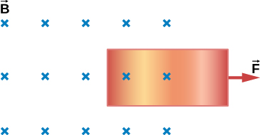
The copper sheet shown below is partially in a magnetic field. When it is pulled to the right, a resisting force pulls it to the left. Explain. What happen if the sheet is pushed to the left?
Problems
Calculate the induced electric field in a 50-turn coil with a diameter of 15 cm that is placed in a spatially uniform magnetic field of magnitude 0.50 T so that the face of the coil and the magnetic field are perpendicular. This magnetic field is reduced to zero in 0.10 seconds. Assume that the magnetic field is cylindrically symmetric with respect to the central axis of the coil.
Show Solution
9.375 V/m
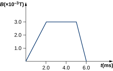
The magnetic field through a circular loop of radius 10.0 cm varies with time as shown in the accompanying figure. The field is perpendicular to the loop. Assuming cylindrical symmetry with respect to the central axis of the loop, plot the induced electric field in the loop as a function of time.
The current I through a long solenoid with n turns per meter and radius R is changing with time as given by dI/dt. Calculate the induced electric field as a function of distance r from the central axis of the solenoid.
Show Solution
Inside, [latex]B={\mu }_{0}nI\text{,}\phantom{\rule{0.5em}{0ex}}\oint \stackrel{\to }{\textbf{E}}·d\stackrel{\to }{\textbf{l}}=\left(\pi {r}^{2}\right){\mu }_{0}n\frac{dI}{dt},[/latex] so, [latex]E=\frac{{\mu }_{0}nr}{2}·\frac{dI}{dt}[/latex] (inside). Outside, [latex]E\left(2\pi r\right)=\pi {R}^{2}{\mu }_{0}n\frac{dI}{dt},[/latex] so, [latex]E=\frac{{\mu }_{0}n{R}^{2}}{2r}·\frac{dI}{dt}[/latex] (outside)
Calculate the electric field induced both inside and outside the solenoid of the preceding problem if [latex]I={I}_{0}\phantom{\rule{0.2em}{0ex}}\text{sin}\phantom{\rule{0.2em}{0ex}}\omega t.[/latex]
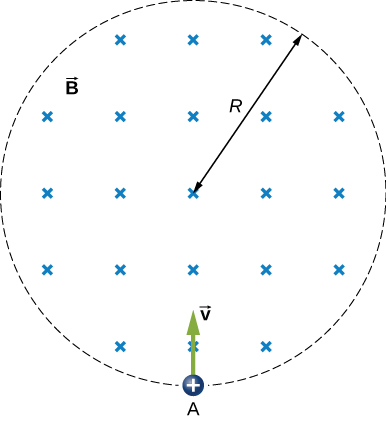
Over a region of radius R, there is a spatially uniform magnetic field [latex]\stackrel{\to }{\textbf{B}}.[/latex] (See below.) At [latex]t=0[/latex], [latex]B=1.0\phantom{\rule{0.2em}{0ex}}\text{T,}[/latex] after which it decreases at a constant rate to zero in 30 s. (a) What is the electric field in the regions where [latex]r\le R[/latex] and [latex]r\ge R[/latex] during that 30-s interval? (b) Assume that [latex]R=10.0\phantom{\rule{0.2em}{0ex}}\text{cm}[/latex]. How much work is done by the electric field on a proton that is carried once clock wise around a circular path of radius 5.0 cm? (c) How much work is done by the electric field on a proton that is carried once counterclockwise around a circular path of any radius [latex]r\ge R[/latex]? (d) At the instant when [latex]B=0.50\phantom{\rule{0.2em}{0ex}}\text{T}[/latex], a proton enters the magnetic field at A, moving a velocity [latex]\stackrel{\to }{\textbf{v}}[/latex] [latex]\left(v=5.0\phantom{\rule{0.2em}{0ex}}×\phantom{\rule{0.2em}{0ex}}{10}^{6}\phantom{\rule{0.2em}{0ex}}\text{m}\text{/}\text{s}\right)[/latex] as shown. What are the electric and magnetic forces on the proton at that instant?
Show Solution
a. [latex]{E}_{\text{inside}}=\frac{r}{2}\phantom{\rule{0.2em}{0ex}}\frac{dB}{dt}[/latex], [latex]{E}_{\text{outside}}=\frac{{r}^{2}}{2R}\phantom{\rule{0.2em}{0ex}}\frac{dB}{dt}[/latex]; b. [latex]W=4.19\phantom{\rule{0.2em}{0ex}}×\phantom{\rule{0.2em}{0ex}}{10}^{-23}\phantom{\rule{0.2em}{0ex}}\text{J}[/latex]; c. 0 J; d. [latex]{F}_{\text{mag}}=4\phantom{\rule{0.2em}{0ex}}×\phantom{\rule{0.2em}{0ex}}{10}^{-13}\phantom{\rule{0.2em}{0ex}}\text{N},[/latex] [latex]{F}_{\text{elec}}=2.7\phantom{\rule{0.2em}{0ex}}×\phantom{\rule{0.2em}{0ex}}{10}^{-22}\phantom{\rule{0.2em}{0ex}}\text{N}[/latex]
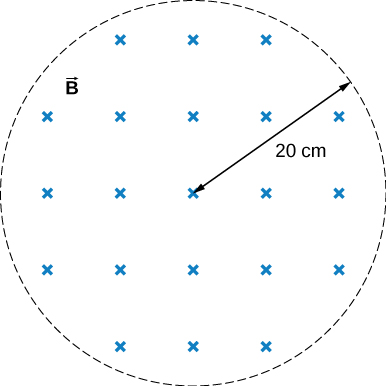
The magnetic field at all points within the cylindrical region whose cross-section is indicated in the accompanying figure starts at 1.0 T and decreases uniformly to zero in 20 s. What is the electric field (both magnitude and direction) as a function of r, the distance from the geometric center of the region?
The current in a long solenoid with 20 turns per centimeter of radius 3 cm is varied with time at a rate of 2 A/s. A circular loop of wire of radius 5 cm and resistance [latex]2\phantom{\rule{0.2em}{0ex}}\text{Ω}[/latex] surrounds the solenoid. Find the electrical current induced in the loop.
Show Solution
[latex]7.1\phantom{\rule{0.2em}{0ex}}\mu \text{A}[/latex]
The current in a long solenoid of radius 3 cm and 20 turns/cm is varied with time at a rate of 2 A/s. Find the electric field at a distance of 4 cm from the center of the solenoid.
Glossary
- induced electric field
- created based on the changing magnetic flux with time
Licenses and Attributions
Induced Electric Fields. Authored by: OpenStax College. Located at: https://openstax.org/books/university-physics-volume-2/pages/13-4-induced-electric-fields. License: CC BY: Attribution. License Terms: Download for free at https://openstax.org/books/university-physics-volume-2/pages/1-introduction
