
Chapter 8. Capacitance
8.5 Molecular Model of a Dielectric
Learning Objectives
By the end of this section, you will be able to:
- Explain the polarization of a dielectric in a uniform electrical field
- Describe the effect of a polarized dielectric on the electrical field between capacitor plates
- Explain dielectric breakdown
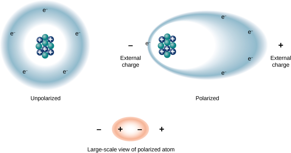
We can understand the effect of a dielectric on capacitance by looking at its behavior at the molecular level. As we have seen in earlier chapters, in general, all molecules can be classified as either polar or nonpolar. There is a net separation of positive and negative charges in an isolated polar molecule, whereas there is no charge separation in an isolated nonpolar molecule (Figure 8.19). In other words, polar molecules have permanent electric-dipole moments and nonpolar molecules do not. For example, a molecule of water is polar, and a molecule of oxygen is nonpolar. Nonpolar molecules can become polar in the presence of an external electrical field, which is called induced polarization.
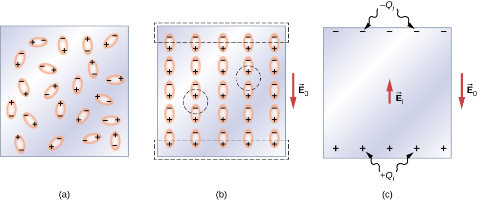
Let’s first consider a dielectric composed of polar molecules. In the absence of any external electrical field, the electric dipoles are oriented randomly, as illustrated in Figure 8.20(a). However, if the dielectric is placed in an external electrical field [latex]{\stackrel{\to }{\textbf{E}}}_{0}[/latex], the polar molecules align with the external field, as shown in part (b) of the figure. Opposite charges on adjacent dipoles within the volume of dielectric neutralize each other, so there is no net charge within the dielectric (see the dashed circles in part (b)). However, this is not the case very close to the upper and lower surfaces that border the dielectric (the region enclosed by the dashed rectangles in part (b)), where the alignment does produce a net charge. Since the external electrical field merely aligns the dipoles, the dielectric as a whole is neutral, and the surface charges induced on its opposite faces are equal and opposite. These induced surface charges [latex]+{Q}_{i}[/latex] and [latex]\text{−}{Q}_{i}[/latex] produce an additional electrical field [latex]{\stackrel{\to }{\textbf{E}}}_{\text{i}}[/latex] (an induced electrical field), which opposes the external field [latex]{\stackrel{\to }{\textbf{E}}}_{0}[/latex], as illustrated in part (c).
The same effect is produced when the molecules of a dielectric are nonpolar. In this case, a nonpolar molecule acquires an induced electric-dipole moment because the external field [latex]{\stackrel{\to }{\textbf{E}}}_{0}[/latex] causes a separation between its positive and negative charges. The induced dipoles of the nonpolar molecules align with [latex]{\stackrel{\to }{\textbf{E}}}_{0}[/latex] in the same way as the permanent dipoles of the polar molecules are aligned (shown in part (b)). Hence, the electrical field within the dielectric is weakened regardless of whether its molecules are polar or nonpolar.
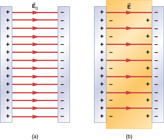
Therefore, when the region between the parallel plates of a charged capacitor, such as that shown in Figure 8.21(a), is filled with a dielectric, within the dielectric there is an electrical field [latex]{\stackrel{\to }{\textbf{E}}}_{0}[/latex] due to the free charge [latex]{Q}_{0}[/latex] on the capacitor plates and an electrical field [latex]{\stackrel{\to }{\textbf{E}}}_{\text{i}}[/latex] due to the induced charge [latex]{Q}_{i}[/latex] on the surfaces of the dielectric. Their vector sum gives the net electrical field [latex]\stackrel{\to }{\textbf{E}}[/latex] within the dielectric between the capacitor plates (shown in part (b) of the figure):
This net field can be considered to be the field produced by an effective charge [latex]{Q}_{0}-{Q}_{i}[/latex] on the capacitor.
In most dielectrics, the net electrical field [latex]\stackrel{\to }{\textbf{E}}[/latex] is proportional to the field [latex]{\stackrel{\to }{\textbf{E}}}_{0}[/latex] produced by the free charge. In terms of these two electrical fields, the dielectric constant [latex]\kappa[/latex] of the material is defined as
Since [latex]{\stackrel{\to }{\textbf{E}}}_{0}[/latex] and [latex]{\stackrel{\to }{\textbf{E}}}_{\text{i}}[/latex] point in opposite directions, the magnitude E is smaller than the magnitude [latex]{E}_{0}[/latex] and therefore [latex]\kappa >1.[/latex] Combining Equation 8.14 with Equation 8.13, and rearranging the terms, yields the following expression for the induced electrical field in a dielectric:
When the magnitude of an external electrical field becomes too large, the molecules of dielectric material start to become ionized. A molecule or an atom is ionized when one or more electrons are removed from it and become free electrons, no longer bound to the molecular or atomic structure. When this happens, the material can conduct, thereby allowing charge to move through the dielectric from one capacitor plate to the other. This phenomenon is called dielectric breakdown. (Figure 8.1 shows typical random-path patterns of electrical discharge during dielectric breakdown.) The critical value, [latex]{E}_{\text{c}}[/latex], of the electrical field at which the molecules of an insulator become ionized is called the dielectric strength of the material. The dielectric strength imposes a limit on the voltage that can be applied for a given plate separation in a capacitor. For example, the dielectric strength of air is [latex]{E}_{\text{c}}=3.0\phantom{\rule{0.2em}{0ex}}\text{MV/m}[/latex], so for an air-filled capacitor with a plate separation of [latex]d=1.00\phantom{\rule{0.2em}{0ex}}\text{mm},[/latex] the limit on the potential difference that can be safely applied across its plates without causing dielectric breakdown is [latex]V={E}_{\text{c}}\text{ }d=\left(3.0\phantom{\rule{0.2em}{0ex}}×\phantom{\rule{0.2em}{0ex}}{10}^{6}\phantom{\rule{0.2em}{0ex}}\text{V/m}\right)\left(1.00\phantom{\rule{0.2em}{0ex}}×\phantom{\rule{0.2em}{0ex}}{10}^{-3}\phantom{\rule{0.2em}{0ex}}\text{m}\right)=3.0\phantom{\rule{0.2em}{0ex}}\text{kV}[/latex].
However, this limit becomes 60.0 kV when the same capacitor is filled with Teflon™, whose dielectric strength is about [latex]60.0\phantom{\rule{0.2em}{0ex}}\text{MV/m}[/latex]. Because of this limit imposed by the dielectric strength, the amount of charge that an air-filled capacitor can store is only [latex]{Q}_{0}={\kappa }_{\text{air}}{C}_{0}\left(3.0\phantom{\rule{0.2em}{0ex}}\text{kV}\right)[/latex] and the charge stored on the same Teflon™-filled capacitor can be as much as
which is about 42 times greater than a charge stored on an air-filled capacitor. Typical values of dielectric constants and dielectric strengths for various materials are given in Table 8.1. Notice that the dielectric constant [latex]\kappa[/latex] is exactly 1.0 for a vacuum (the empty space serves as a reference condition) and very close to 1.0 for air under normal conditions (normal pressure at room temperature). These two values are so close that, in fact, the properties of an air-filled capacitor are essentially the same as those of an empty capacitor.
| Material | Dielectric constant [latex]\kappa[/latex] | Dielectric strength [latex]{E}_{\text{c}}\left[\phantom{\rule{0.2em}{0ex}}×\phantom{\rule{0.2em}{0ex}}{10}^{6}\text{V}\text{/}\text{m}\right][/latex] |
|---|---|---|
| Vacuum | 1 | ∞ |
| Dry air (1 atm) | 1.00059 | 3.0 |
| Teflon™ | 2.1 | 60 to 173 |
| Paraffin | 2.3 | 11 |
| Silicon oil | 2.5 | 10 to 15 |
| Polystyrene | 2.56 | 19.7 |
| Nylon | 3.4 | 14 |
| Paper | 3.7 | 16 |
| Fused quartz | 3.78 | 8 |
| Glass | 4 to 6 | 9.8 to 13.8 |
| Concrete | 4.5 | – |
| Bakelite | 4.9 | 24 |
| Diamond | 5.5 | 2,000 |
| Pyrex glass | 5.6 | 14 |
| Mica | 6.0 | 118 |
| Neoprene rubber | 6.7 | 15.7 to 26.7 |
| Water | 80 | [latex]-[/latex] |
| Sulfuric acid | 84 to 100 | [latex]-[/latex] |
| Titanium dioxide | 86 to 173 | – |
| Strontium titanate | 310 | 8 |
| Barium titanate | 1,200 to 10,000 | – |
| Calcium copper titanate | > 250,000 | – |
Not all substances listed in the table are good insulators, despite their high dielectric constants. Water, for example, consists of polar molecules and has a large dielectric constant of about 80. In a water molecule, electrons are more likely found around the oxygen nucleus than around the hydrogen nuclei. This makes the oxygen end of the molecule slightly negative and leaves the hydrogens end slightly positive, which makes the molecule easy to align along an external electrical field, and thus water has a large dielectric constant. However, the polar nature of water molecules also makes water a good solvent for many substances, which produces undesirable effects, because any concentration of free ions in water conducts electricity.
Example
Electrical Field and Induced Surface Charge
Suppose that the distance between the plates of the capacitor in Example 8.10 is 2.0 mm and the area of each plate is [latex]4.5\phantom{\rule{0.2em}{0ex}}×\phantom{\rule{0.2em}{0ex}}{10}^{-3}\phantom{\rule{0.2em}{0ex}}{\text{m}}^{2}[/latex]. Determine: (a) the electrical field between the plates before and after the Teflon™ is inserted, and (b) the surface charge induced on the Teflon™ surfaces.
Strategy
In part (a), we know that the voltage across the empty capacitor is [latex]{V}_{0}=40\phantom{\rule{0.2em}{0ex}}\text{V}[/latex], so to find the electrical fields we use the relation [latex]V=Ed[/latex] and Equation 8.14. In part (b), knowing the magnitude of the electrical field, we use the expression for the magnitude of electrical field near a charged plate [latex]E=\sigma \text{/}{\epsilon }_{0}[/latex], where [latex]\sigma[/latex] is a uniform surface charge density caused by the surface charge. We use the value of free charge [latex]{Q}_{0}=8.0\phantom{\rule{0.2em}{0ex}}×\phantom{\rule{0.2em}{0ex}}{10}^{-10}\phantom{\rule{0.2em}{0ex}}\text{C}[/latex] obtained in Example 8.10.
Solution
Show Answer
- The electrical field [latex]{E}_{0}[/latex] between the plates of an empty capacitor is
[latex]{E}_{0}=\frac{{V}_{0}}{d}=\frac{40\phantom{\rule{0.2em}{0ex}}\text{V}}{2.0\phantom{\rule{0.2em}{0ex}}×\phantom{\rule{0.2em}{0ex}}{10}^{-3}\text{m}}=2.0\phantom{\rule{0.2em}{0ex}}×\phantom{\rule{0.2em}{0ex}}{10}^{4}\phantom{\rule{0.2em}{0ex}}\text{V/m}.[/latex]
The electrical field E with the Teflon™ in place is
[latex]E=\frac{1}{\kappa }{E}_{0}=\frac{1}{2.1}2.0\phantom{\rule{0.2em}{0ex}}×\phantom{\rule{0.2em}{0ex}}{10}^{4}\phantom{\rule{0.2em}{0ex}}\text{V/m}=9.5\phantom{\rule{0.2em}{0ex}}×\phantom{\rule{0.2em}{0ex}}{10}^{3}\phantom{\rule{0.2em}{0ex}}\text{V/m}\text{.}[/latex] - The effective charge on the capacitor is the difference between the free charge [latex]{Q}_{0}[/latex] and the induced charge [latex]{Q}_{\text{i}}[/latex]. The electrical field in the Teflon™ is caused by this effective charge. Thus
[latex]E=\frac{1}{{\epsilon }_{0}}\sigma =\frac{1}{{\epsilon }_{0}}\phantom{\rule{0.2em}{0ex}}\frac{{Q}_{0}-{Q}_{\text{i}}}{A}.[/latex]
We invert this equation to obtain [latex]{Q}_{\text{i}}[/latex], which yields
[latex]\begin{array}{cc}\hfill {Q}_{\text{i}}& ={Q}_{0}-{\epsilon }_{0}AE\hfill \\ & =8.0\phantom{\rule{0.2em}{0ex}}×\phantom{\rule{0.2em}{0ex}}{10}^{-10}\text{C}-\left(8.85\phantom{\rule{0.2em}{0ex}}×\phantom{\rule{0.2em}{0ex}}{10}^{-12}\phantom{\rule{0.2em}{0ex}}\frac{{\text{C}}^{2}}{\text{N}·{\text{m}}^{2}}\right)\left(4.5\phantom{\rule{0.2em}{0ex}}×\phantom{\rule{0.2em}{0ex}}{10}^{-3}\phantom{\rule{0.2em}{0ex}}{\text{m}}^{2}\right)\left(9.5\phantom{\rule{0.2em}{0ex}}×\phantom{\rule{0.2em}{0ex}}{10}^{3}\phantom{\rule{0.2em}{0ex}}\frac{\text{V}}{\text{m}}\right)\hfill \\ & =4.2\phantom{\rule{0.2em}{0ex}}×\phantom{\rule{0.2em}{0ex}}{10}^{-10}\text{C}=0.42\phantom{\rule{0.2em}{0ex}}\text{nC}\text{.}\hfill \end{array}[/latex]
Example
Inserting a Dielectric into a Capacitor Connected to a Battery
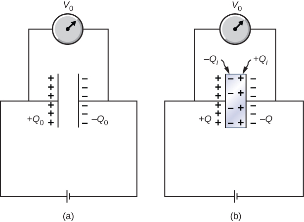
When a battery of voltage [latex]{V}_{0}[/latex] is connected across an empty capacitor of capacitance [latex]{C}_{0}[/latex], the charge on its plates is [latex]{Q}_{0}[/latex], and the electrical field between its plates is [latex]{E}_{0}[/latex]. A dielectric of dielectric constant [latex]\kappa[/latex] is inserted between the plates while the battery remains in place, as shown in Figure 8.22. (a) Find the capacitance C, the voltage V across the capacitor, and the electrical field E between the plates after the dielectric is inserted. (b) Obtain an expression for the free charge Q on the plates of the filled capacitor and the induced charge [latex]{Q}_{\text{i}}[/latex] on the dielectric surface in terms of the original plate charge [latex]{Q}_{0}[/latex].
Strategy
We identify the known values: [latex]{V}_{0}[/latex], [latex]{C}_{0}[/latex],[latex]{E}_{0}[/latex], [latex]\kappa[/latex], and [latex]{Q}_{0}[/latex]. Our task is to express the unknown values in terms of these known values.
Solution
Show Answer
(a) The capacitance of the filled capacitor is [latex]C=\kappa {C}_{0}[/latex]. Since the battery is always connected to the capacitor plates, the potential difference between them does not change; hence, [latex]V={V}_{0}[/latex]. Because of that, the electrical field in the filled capacitor is the same as the field in the empty capacitor, so we can obtain directly that
(b) For the filled capacitor, the free charge on the plates is
The electrical field E in the filled capacitor is due to the effective charge [latex]Q-{Q}_{\text{i}}[/latex] (Figure 8.22(b)). Since [latex]E={E}_{0}[/latex], we have
Solving this equation for [latex]{Q}_{\text{i}}[/latex], we obtain for the induced charge
Significance
Notice that for materials with dielectric constants larger than 2 (see Table 8.1), the induced charge on the surface of dielectric is larger than the charge on the plates of a vacuum capacitor. The opposite is true for gasses like air whose dielectric constant is smaller than 2.
Check Your Understanding
Continuing with Example 8.12, show that when the battery is connected across the plates the energy stored in dielectric-filled capacitor is [latex]U=\kappa {U}_{0}[/latex] (larger than the energy [latex]{U}_{0}[/latex] of an empty capacitor kept at the same voltage). Compare this result with the result [latex]U={U}_{0}\text{/}\kappa[/latex] found previously for an isolated, charged capacitor.
Check Your Understanding
Repeat the calculations of Example 8.10 for the case in which the battery remains connected while the dielectric is placed in the capacitor.
Show Solution
a. [latex]{C}_{0}=20\phantom{\rule{0.2em}{0ex}}\text{pF}[/latex], [latex]C=42\phantom{\rule{0.2em}{0ex}}\text{pF}[/latex]; b. [latex]{Q}_{0}=0.8\phantom{\rule{0.2em}{0ex}}\text{nC}[/latex], [latex]Q=1.7\phantom{\rule{0.2em}{0ex}}\text{nC}[/latex]; c. [latex]{V}_{0}=V=40\phantom{\rule{0.2em}{0ex}}\text{V}[/latex]; d. [latex]{U}_{0}=16\phantom{\rule{0.2em}{0ex}}\text{nJ}[/latex], [latex]U=34\phantom{\rule{0.2em}{0ex}}\text{nJ}[/latex]
Summary
- When a dielectric is inserted between the plates of a capacitor, equal and opposite surface charge is induced on the two faces of the dielectric. The induced surface charge produces an induced electrical field that opposes the field of the free charge on the capacitor plates.
- The dielectric constant of a material is the ratio of the electrical field in vacuum to the net electrical field in the material. A capacitor filled with dielectric has a larger capacitance than an empty capacitor.
- The dielectric strength of an insulator represents a critical value of electrical field at which the molecules in an insulating material start to become ionized. When this happens, the material can conduct and dielectric breakdown is observed.
Key Equations
| Capacitance | [latex]C=\frac{Q}{V}[/latex] |
| Capacitance of a parallel-plate capacitor | [latex]C={\epsilon }_{0}\frac{A}{d}[/latex] |
| Capacitance of a vacuum spherical capacitor | [latex]C=4\pi {\epsilon }_{0}\frac{{R}_{1}{R}_{2}}{{R}_{2}-{R}_{1}}[/latex] |
| Capacitance of a vacuum cylindrical capacitor | [latex]C=\frac{2\pi {\epsilon }_{0}l}{\text{ln}\left({R}_{2}\text{/}{R}_{1}\right)}[/latex] |
| Capacitance of a series combination | [latex]\frac{1}{{C}_{\text{S}}}=\frac{1}{{C}_{1}}+\frac{1}{{C}_{2}}+\frac{1}{{C}_{3}}+\text{⋯}[/latex] |
| Capacitance of a parallel combination | [latex]{C}_{\text{P}}={C}_{1}+{C}_{2}+{C}_{3}+\text{⋯}[/latex] |
| Energy density | [latex]{u}_{E}=\frac{1}{2}{\epsilon }_{0}{E}^{2}[/latex] |
| Energy stored in a capacitor | [latex]{U}_{C}=\frac{1}{2}{V}^{2}C=\frac{1}{2}\phantom{\rule{0.2em}{0ex}}\frac{{Q}^{2}}{C}=\frac{1}{2}QV[/latex] |
| Capacitance of a capacitor with dielectric | [latex]C=\kappa {C}_{0}[/latex] |
| Energy stored in an isolated capacitor with dielectric |
[latex]U=\frac{1}{\kappa }{U}_{0}[/latex] |
| Dielectric constant | [latex]\kappa =\frac{{E}_{0}}{E}[/latex] |
| Induced electrical field in a dielectric | [latex]{\stackrel{\to }{\textbf{E}}}_{\text{i}}=\left(\frac{1}{\kappa }-1\right){\stackrel{\to }{\textbf{E}}}_{0}[/latex] |
Conceptual Questions
Distinguish between dielectric strength and dielectric constant.
Show Solution
Dielectric strength is a critical value of an electrical field above which an insulator starts to conduct; a dielectric constant is the ratio of the electrical field in vacuum to the net electrical field in a material.
Water is a good solvent because it has a high dielectric constant. Explain.
Water has a high dielectric constant. Explain why it is then not used as a dielectric material in capacitors.
Show Solution
Water is a good solvent.
Elaborate on why molecules in a dielectric material experience net forces on them in a non-uniform electrical field but not in a uniform field.
Explain why the dielectric constant of a substance containing permanent molecular electric dipoles decreases with increasing temperature.
Show Solution
When energy of thermal motion is large (high temperature), an electrical field must be large too in order to keep electric dipoles aligned with it.
Give a reason why a dielectric material increases capacitance compared with what it would be with air between the plates of a capacitor. How does a dielectric material also allow a greater voltage to be applied to a capacitor? (The dielectric thus increases C and permits a greater V.)
Elaborate on the way in which the polar character of water molecules helps to explain water’s relatively large dielectric constant.
Show Solution
answers may vary
Sparks will occur between the plates of an air-filled capacitor at a lower voltage when the air is humid than when it is dry. Discuss why, considering the polar character of water molecules.
Problems
Two flat plates containing equal and opposite charges are separated by material 4.0 mm thick with a dielectric constant of 5.0. If the electrical field in the dielectric is 1.5 MV/m, what are (a) the charge density on the capacitor plates, and (b) the induced charge density on the surfaces of the dielectric?
For a Teflon™-filled, parallel-plate capacitor, the area of the plate is [latex]50.0\phantom{\rule{0.2em}{0ex}}{\text{cm}}^{2}[/latex] and the spacing between the plates is 0.50 mm. If the capacitor is connected to a 200-V battery, find (a) the free charge on the capacitor plates, (b) the electrical field in the dielectric, and (c) the induced charge on the dielectric surfaces.
Show Solution
a. 37 nC; b. 0.4 MV/m; c. 19 nC
Find the capacitance of a parallel-plate capacitor having plates with a surface area of [latex]5.00\phantom{\rule{0.2em}{0ex}}{m}^{2}[/latex] and separated by 0.100 mm of Teflon™.
(a) What is the capacitance of a parallel-plate capacitor with plates of area [latex]1.50\phantom{\rule{0.2em}{0ex}}{\text{m}}^{2}[/latex] that are separated by 0.0200 mm of neoprene rubber? (b) What charge does it hold when 9.00 V is applied to it?
Show Solution
a. [latex]4.4\phantom{\rule{0.2em}{0ex}}\text{μ}\text{F}[/latex]; b. [latex]4.0\phantom{\rule{0.2em}{0ex}}×\phantom{\rule{0.2em}{0ex}}{10}^{\text{-5}}\phantom{\rule{0.2em}{0ex}}\text{C}[/latex]
Two parallel plates have equal and opposite charges. When the space between the plates is evacuated, the electrical field is [latex]E=3.20\phantom{\rule{0.2em}{0ex}}×\phantom{\rule{0.2em}{0ex}}{10}^{5}\phantom{\rule{0.2em}{0ex}}\text{V}\text{/}\text{m}[/latex]. When the space is filled with dielectric, the electrical field is [latex]E=2.50\phantom{\rule{0.2em}{0ex}}×\phantom{\rule{0.2em}{0ex}}{10}^{5}\phantom{\rule{0.2em}{0ex}}\text{V}\text{/}\text{m}[/latex]. (a) What is the surface charge density on each surface of the dielectric? (b) What is the dielectric constant?
The dielectric to be used in a parallel-plate capacitor has a dielectric constant of 3.60 and a dielectric strength of [latex]1.60\phantom{\rule{0.2em}{0ex}}×\phantom{\rule{0.2em}{0ex}}{10}^{7}\phantom{\rule{0.2em}{0ex}}\text{V}\text{/}\text{m}[/latex]. The capacitor has to have a capacitance of 1.25 nF and must be able to withstand a maximum potential difference 5.5 kV. What is the minimum area the plates of the capacitor may have?
Show Solution
[latex]0.0135\phantom{\rule{0.2em}{0ex}}{\text{m}}^{2}[/latex]
When a 360-nF air capacitor is connected to a power supply, the energy stored in the capacitor is [latex]18.5\phantom{\rule{0.2em}{0ex}}\mu \text{J}[/latex]. While the capacitor is connected to the power supply, a slab of dielectric is inserted that completely fills the space between the plates. This increases the stored energy by [latex]23.2\phantom{\rule{0.2em}{0ex}}\mu \text{J}[/latex]. (a) What is the potential difference between the capacitor plates? (b) What is the dielectric constant of the slab?
A parallel-plate capacitor has square plates that are 8.00 cm on each side and 3.80 mm apart. The space between the plates is completely filled with two square slabs of dielectric, each 8.00 cm on a side and 1.90 mm thick. One slab is Pyrex glass and the other slab is polystyrene. If the potential difference between the plates is 86.0 V, find how much electrical energy can be stored in this capacitor.
Show Solution
[latex]0.185\phantom{\rule{0.2em}{0ex}}\mu \text{J}[/latex]
Additional Problems
A capacitor is made from two flat parallel plates placed 0.40 mm apart. When a charge of [latex]0.020\phantom{\rule{0.2em}{0ex}}\text{μ}\text{C}[/latex] is placed on the plates the potential difference between them is 250 V. (a) What is the capacitance of the plates? (b) What is the area of each plate? (c) What is the charge on the plates when the potential difference between them is 500 V? (d) What maximum potential difference can be applied between the plates so that the magnitude of electrical fields between the plates does not exceed 3.0 MV/m?
An air-filled (empty) parallel-plate capacitor is made from two square plates that are 25 cm on each side and 1.0 mm apart. The capacitor is connected to a 50-V battery and fully charged. It is then disconnected from the battery and its plates are pulled apart to a separation of 2.00 mm. (a) What is the capacitance of this new capacitor? (b) What is the charge on each plate? (c) What is the electrical field between the plates?
Show Solution
a. 0.277 nF; b. 27.7 nC; c. 50 kV/m
Suppose that the capacitance of a variable capacitor can be manually changed from 100 to 800 pF by turning a dial connected to one set of plates by a shaft, from [latex]0\text{°}[/latex] to [latex]180\text{°}[/latex]. With the dial set at [latex]180\text{°}[/latex] (corresponding to [latex]C=800\phantom{\rule{0.2em}{0ex}}\text{pF}[/latex]), the capacitor is connected to a 500-V source. After charging, the capacitor is disconnected from the source, and the dial is turned to [latex]0\text{°}[/latex]. (a) What is the charge on the capacitor? (b) What is the voltage across the capacitor when the dial is set to [latex]0\text{°}\text{?}[/latex]
Earth can be considered as a spherical capacitor with two plates, where the negative plate is the surface of Earth and the positive plate is the bottom of the ionosphere, which is located at an altitude of approximately 70 km. The potential difference between Earth’s surface and the ionosphere is about 350,000 V. (a) Calculate the capacitance of this system. (b) Find the total charge on this capacitor. (c) Find the energy stored in this system.
Show Solution
a. 0.065 F; b. 23,000 C; c. 4.0 GJ
A [latex]4.00\text{-}\mu \text{F}[/latex] capacitor and a [latex]6.00\text{-}\mu \text{F}[/latex] capacitor are connected in parallel across a 600-V supply line. (a) Find the charge on each capacitor and voltage across each. (b) The charged capacitors are disconnected from the line and from each other. They are then reconnected to each other with terminals of unlike sign together. Find the final charge on each capacitor and the voltage across each.
Three capacitors having capacitances of 8.40, 8.40, and 4.20 [latex]\text{μ}\text{F}[/latex], respectively, are connected in series across a 36.0-V potential difference. (a) What is the charge on the [latex]4.20\text{-}\text{μ}\text{F}[/latex] capacitor? (b) The capacitors are disconnected from the potential difference without allowing them to discharge. They are then reconnected in parallel with each other with the positively charged plates connected together. What is the voltage across each capacitor in the parallel combination?
Show Solution
a. [latex]75.6\phantom{\rule{0.2em}{0ex}}\text{μ}\text{C}[/latex]; b. 10.8 V
A parallel-plate capacitor with capacitance [latex]5.0\phantom{\rule{0.2em}{0ex}}\text{μ}\text{F}[/latex] is charged with a 12.0-V battery, after which the battery is disconnected. Determine the minimum work required to increase the separation between the plates by a factor of 3.
(a) How much energy is stored in the electrical fields in the capacitors (in total) shown below? (b) Is this energy equal to the work done by the 400-V source in charging the capacitors?
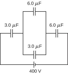
Show Solution
a. 0.13 J; b. no, because of resistive heating in connecting wires that is always present, but the circuit schematic does not indicate resistors
Three capacitors having capacitances 8.4, 8.4, and 4.2 [latex]\text{μ}\text{F}[/latex] are connected in series across a 36.0-V potential difference. (a) What is the total energy stored in all three capacitors? (b) The capacitors are disconnected from the potential difference without allowing them to discharge. They are then reconnected in parallel with each other with the positively charged plates connected together. What is the total energy now stored in the capacitors?
(a) An [latex]8.00\text{-}\mu \text{F}[/latex] capacitor is connected in parallel to another capacitor, producing a total capacitance of [latex]5.00\phantom{\rule{0.2em}{0ex}}\mu \text{F}[/latex]. What is the capacitance of the second capacitor? (b) What is unreasonable about this result? (c) Which assumptions are unreasonable or inconsistent?
Show Solution
a. [latex]\text{−3.00}\phantom{\rule{0.2em}{0ex}}\text{μ}\text{F}[/latex]; b. You cannot have a negative [latex]{C}_{2}[/latex] capacitance. c. The assumption that they were hooked up in parallel, rather than in series, is incorrect. A parallel connection always produces a greater capacitance, while here a smaller capacitance was assumed. This could only happen if the capacitors are connected in series.
(a) On a particular day, it takes [latex]9.60\phantom{\rule{0.2em}{0ex}}×\phantom{\rule{0.2em}{0ex}}{10}^{3}\phantom{\rule{0.2em}{0ex}}\text{J}[/latex] of electrical energy to start a truck’s engine. Calculate the capacitance of a capacitor that could store that amount of energy at 12.0 V. (b) What is unreasonable about this result? (c) Which assumptions are responsible?
(a) A certain parallel-plate capacitor has plates of area [latex]4.00\phantom{\rule{0.2em}{0ex}}{\text{m}}^{2}[/latex], separated by 0.0100 mm of nylon, and stores 0.170 C of charge. What is the applied voltage? (b) What is unreasonable about this result? (c) Which assumptions are responsible or inconsistent?
Show Solution
a. 14.2 kV; b. The voltage is unreasonably large, more than 100 times the breakdown voltage of nylon. c. The assumed charge is unreasonably large and cannot be stored in a capacitor of these dimensions.
A prankster applies 450 V to an [latex]80.0\text{-}\mu \text{F}[/latex] capacitor and then tosses it to an unsuspecting victim. The victim’s finger is burned by the discharge of the capacitor through 0.200 g of flesh. Estimate, what is the temperature increase of the flesh? Is it reasonable to assume that no thermodynamic phase change happened?
Challenge Problems
A spherical capacitor is formed from two concentric spherical conducting spheres separated by vacuum. The inner sphere has radius 12.5 cm and the outer sphere has radius 14.8 cm. A potential difference of 120 V is applied to the capacitor. (a) What is the capacitance of the capacitor? (b) What is the magnitude of the electrical field at [latex]r=12.6\phantom{\rule{0.2em}{0ex}}\text{cm}[/latex], just outside the inner sphere? (c) What is the magnitude of the electrical field at [latex]r=14.7\phantom{\rule{0.2em}{0ex}}\text{cm}[/latex], just inside the outer sphere? (d) For a parallel-plate capacitor the electrical field is uniform in the region between the plates, except near the edges of the plates. Is this also true for a spherical capacitor?
Show Solution
a. 89.6 pF; b. 6.09 kV/m; c. 4.47 kV/m; d. no
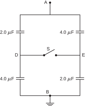
The network of capacitors shown below are all uncharged when a 300-V potential is applied between points A and B with the switch S open. (a) What is the potential difference [latex]{V}_{E}-{V}_{D}[/latex] ? (b) What is the potential at point E after the switch is closed? (c) How much charge flows through the switch after it is closed?
Electronic flash units for cameras contain a capacitor for storing the energy used to produce the flash. In one such unit the flash lasts for 1/675 fraction of a second with an average light power output of 270 kW. (a) If the conversion of electrical energy to light is 95% efficient (because the rest of the energy goes to thermal energy), how much energy must be stored in the capacitor for one flash? (b) The capacitor has a potential difference between its plates of 125 V when the stored energy equals the value stored in part (a). What is the capacitance?
Show Solution
a. 421 J; b. 53.9 mF
A spherical capacitor is formed from two concentric spherical conducting shells separated by a vacuum. The inner sphere has radius 12.5 cm and the outer sphere has radius 14.8 cm. A potential difference of 120 V is applied to the capacitor. (a) What is the energy density at [latex]r=12.6\phantom{\rule{0.2em}{0ex}}\text{cm}[/latex], just outside the inner sphere? (b) What is the energy density at [latex]r=14.7\phantom{\rule{0.2em}{0ex}}\text{cm}[/latex], just inside the outer sphere? (c) For the parallel-plate capacitor the energy density is uniform in the region between the plates, except near the edges of the plates. Is this also true for the spherical capacitor?
A metal plate of thickness t is held in place between two capacitor plates by plastic pegs, as shown below. The effect of the pegs on the capacitance is negligible. The area of each capacitor plate and the area of the top and bottom surfaces of the inserted plate are all A. What is the capacitance of this system?
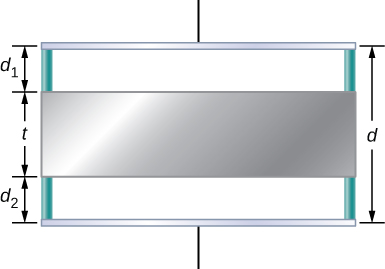
Show Solution
[latex]C={\epsilon }_{0}A\text{/}\left({d}_{1}+{d}_{2}\right)[/latex]
A parallel-plate capacitor is filled with two dielectrics, as shown below. When the plate area is A and separation between plates is d, show that the capacitance is given by
[latex]C={\epsilon }_{0}\frac{A}{d}\phantom{\rule{0.2em}{0ex}}\frac{{\kappa }_{1}+{\kappa }_{2}}{2}.[/latex]
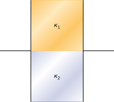
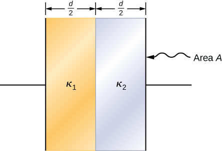
A parallel-plate capacitor is filled with two dielectrics, as shown below. Show that the capacitance is given by
[latex]C=2{\epsilon }_{0}\frac{A}{d}\phantom{\rule{0.2em}{0ex}}\frac{{\kappa }_{1}{\kappa }_{2}}{{\kappa }_{1}+{\kappa }_{2}}.[/latex]
Show Solution
proof
A capacitor has parallel plates of area [latex]12\phantom{\rule{0.2em}{0ex}}{\text{cm}}^{2}[/latex] separated by 2.0 mm. The space between the plates is filled with polystyrene. (a) Find the maximum permissible voltage across the capacitor to avoid dielectric breakdown. (b) When the voltage equals the value found in part (a), find the surface charge density on the surface of the dielectric.
Glossary
- dielectric breakdown
- phenomenon that occurs when an insulator becomes a conductor in a strong electrical field
- dielectric strength
- critical electrical field strength above which molecules in insulator begin to break down and the insulator starts to conduct
- induced electric-dipole moment
- dipole moment that a nonpolar molecule may acquire when it is placed in an electrical field
- induced electrical field
- electrical field in the dielectric due to the presence of induced charges
- induced surface charges
- charges that occur on a dielectric surface due to its polarization
Licenses and Attributions
Molecular Model of a Dielectric. Authored by: OpenStax College. Located at: https://openstax.org/books/university-physics-volume-2/pages/8-5-molecular-model-of-a-dielectric. License: CC BY: Attribution. License Terms: Download for free at https://openstax.org/books/university-physics-volume-2/pages/1-introduction
