
Chapter 10. Direct-Current Circuits
10.6 Household Wiring and Electrical Safety
Learning Objectives
By the end of the section, you will be able to:
- List the basic concepts involved in house wiring
- Define the terms thermal hazard and shock hazard
- Describe the effects of electrical shock on human physiology and their relationship to the amount of current through the body
- Explain the function of fuses and circuit breakers
Electricity presents two known hazards: thermal and shock. A thermal hazard is one in which an excessive electric current causes undesired thermal effects, such as starting a fire in the wall of a house. A shock hazard occurs when an electric current passes through a person. Shocks range in severity from painful, but otherwise harmless, to heart-stopping lethality. In this section, we consider these hazards and the various factors affecting them in a quantitative manner. We also examine systems and devices for preventing electrical hazards.
Thermal Hazards
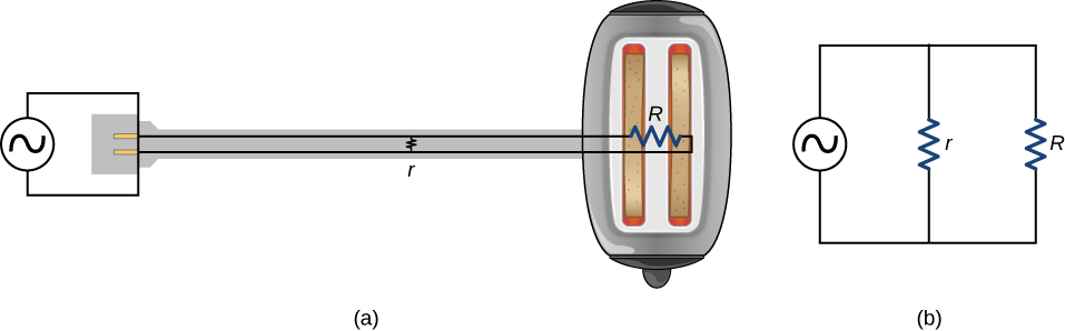
Electric power causes undesired heating effects whenever electric energy is converted into thermal energy at a rate faster than it can be safely dissipated. A classic example of this is the short circuit, a low-resistance path between terminals of a voltage source. An example of a short circuit is shown in Figure 10.41. A toaster is plugged into a common household electrical outlet. Insulation on wires leading to an appliance has worn through, allowing the two wires to come into contact, or “short.” As a result, thermal energy can quickly raise the temperature of surrounding materials, melting the insulation and perhaps causing a fire.
The circuit diagram shows a symbol that consists of a sine wave enclosed in a circle. This symbol represents an alternating current (ac) voltage source. In an ac voltage source, the voltage oscillates between a positive and negative maximum amplitude. Up to now, we have been considering direct current (dc) voltage sources, but many of the same concepts are applicable to ac circuits.
Another serious thermal hazard occurs when wires supplying power to an appliance are overloaded. Electrical wires and appliances are often rated for the maximum current they can safely handle. The term “overloaded” refers to a condition where the current exceeds the rated maximum current. As current flows through a wire, the power dissipated in the supply wires is [latex]P={I}^{2}{R}_{\text{W}},[/latex] where [latex]{R}_{\text{W}}[/latex] is the resistance of the wires and I is the current flowing through the wires. If either I or [latex]{R}_{\text{W}}[/latex] is too large, the wires overheat. Fuses and circuit breakers are used to limit excessive currents.
Shock Hazards
Electric shock is the physiological reaction or injury caused by an external electric current passing through the body. The effect of an electric shock can be negative or positive. When a current with a magnitude above 300 mA passes through the heart, death may occur. Most electrical shock fatalities occur because a current causes ventricular fibrillation, a massively irregular and often fatal, beating of the heart. On the other hand, a heart attack victim, whose heart is in fibrillation, can be saved by an electric shock from a defibrillator.
The effects of an undesirable electric shock can vary in severity: a slight sensation at the point of contact, pain, loss of voluntary muscle control, difficulty breathing, heart fibrillation, and possibly death. The loss of voluntary muscle control can cause the victim to not be able to let go of the source of the current.
The major factors upon which the severity of the effects of electrical shock depend are
- The amount of current I
- The path taken by the current
- The duration of the shock
- The frequency f of the current ([latex]f=0[/latex] for dc)
Our bodies are relatively good electric conductors due to the body’s water content. A dangerous condition occurs when the body is in contact with a voltage source and “ground.” The term “ground” refers to a large sink or source of electrons, for example, the earth (thus, the name). When there is a direct path to ground, large currents will pass through the parts of the body with the lowest resistance and a direct path to ground. A safety precaution used by many professions is the wearing of insulated shoes. Insulated shoes prohibit a pathway to ground for electrons through the feet by providing a large resistance. Whenever working with high-power tools, or any electric circuit, ensure that you do not provide a pathway for current flow (especially across the heart). A common safety precaution is to work with one hand, reducing the possibility of providing a current path through the heart.
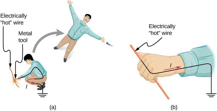
Very small currents pass harmlessly and unfelt through the body. This happens to you regularly without your knowledge. The threshold of sensation is only 1 mA and, although unpleasant, shocks are apparently harmless for currents less than 5 mA. A great number of safety rules take the 5-mA value for the maximum allowed shock. At 5–30 mA and above, the current can stimulate sustained muscular contractions, much as regular nerve impulses do (Figure 10.42). Very large currents (above 300 mA) cause the heart and diaphragm of the lung to contract for the duration of the shock. Both the heart and respiration stop. Both often return to normal following the shock.
Current is the major factor determining shock severity. A larger voltage is more hazardous, but since [latex]I=V\text{/}R,[/latex] the severity of the shock depends on the combination of voltage and resistance. For example, a person with dry skin has a resistance of about [latex]200\phantom{\rule{0.2em}{0ex}}\text{k}\text{Ω}[/latex]. If he comes into contact with 120-V ac, a current
passes harmlessly through him. The same person soaking wet may have a resistance of [latex]10.0\phantom{\rule{0.2em}{0ex}}\text{k}\text{Ω}[/latex] and the same 120 V will produce a current of 12 mA—above the “can’t let go” threshold and potentially dangerous.
Electrical Safety: Systems and Devices
Figure 10.43(a) shows the schematic for a simple ac circuit with no safety features. This is not how power is distributed in practice. Modern household and industrial wiring requires the three-wire system, shown schematically in part (b), which has several safety features, with live, neutral, and ground wires. First is the familiar circuit breaker (or fuse) to prevent thermal overload. Second is a protective case around the appliance, such as a toaster or refrigerator. The case’s safety feature is that it prevents a person from touching exposed wires and coming into electrical contact with the circuit, helping prevent shocks.
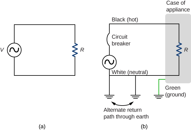
There are three connections to ground shown in Figure 10.43(b). Recall that a ground connection is a low-resistance path directly to ground. The two ground connections on the neutral wire force it to be at zero volts relative to ground, giving the wire its name. This wire is therefore safe to touch even if its insulation, usually white, is missing. The neutral wire is the return path for the current to follow to complete the circuit. Furthermore, the two ground connections supply an alternative path through ground (a good conductor) to complete the circuit. The ground connection closest to the power source could be at the generating plant, whereas the other is at the user’s location. The third ground is to the case of the appliance, through the green ground wire, forcing the case, too, to be at zero volts. The live or hot wire (hereafter referred to as “live/hot”) supplies voltage and current to operate the appliance. Figure 10.44 shows a more pictorial version of how the three-wire system is connected through a three-prong plug to an appliance.
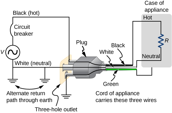
Insulating plastic is color-coded to identify live/hot, neutral, and ground wires, but these codes vary around the world. It is essential to determine the color code in your region. Striped coatings are sometimes used for the benefit of those who are colorblind.
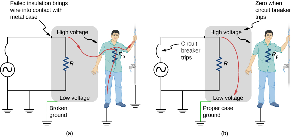
Grounding the case solves more than one problem. The simplest problem is worn insulation on the live/hot wire that allows it to contact the case, as shown in Figure 10.45. Lacking a ground connection, a severe shock is possible. This is particularly dangerous in the kitchen, where a good connection to ground is available through water on the floor or a water faucet. With the ground connection intact, the circuit breaker will trip, forcing repair of the appliance.
A ground fault circuit interrupter (GFCI) is a safety device found in updated kitchen and bathroom wiring that works based on electromagnetic induction. GFCIs compare the currents in the live/hot and neutral wires. When live/hot and neutral currents are not equal, it is almost always because current in the neutral is less than in the live/hot wire. Then some of the current, called a leakage current, is returning to the voltage source by a path other than through the neutral wire. It is assumed that this path presents a hazard. GFCIs are usually set to interrupt the circuit if the leakage current is greater than 5 mA, the accepted maximum harmless shock. Even if the leakage current goes safely to ground through an intact ground wire, the GFCI will trip, forcing repair of the leakage.
Summary
- The two types of electric hazards are thermal (excessive power) and shock (current through a person). Electrical safety systems and devices are employed to prevent thermal and shock hazards.
- Shock severity is determined by current, path, duration, and ac frequency.
- Circuit breakers and fuses interrupt excessive currents to prevent thermal hazards.
- The three-wire system guards against thermal and shock hazards, utilizing live/hot, neutral, and ground wires, and grounding the neutral wire and case of the appliance.
- A ground fault circuit interrupter (GFCI) prevents shock by detecting the loss of current to unintentional paths.
Key Equations
| Terminal voltage of a single voltage source | [latex]{V}_{\text{terminal}}=\epsilon -I{r}_{\text{eq}}[/latex] |
| Equivalent resistance of a series circuit | [latex]{R}_{\text{eq}}={R}_{1}+{R}_{2}+{R}_{3}+\text{⋯}+{R}_{N-1}+{R}_{N}=\sum _{i=1}^{N}{R}_{i}[/latex] |
| Equivalent resistance of a parallel circuit | [latex]{R}_{\text{eq}}={\left(\frac{1}{{R}_{1}}+\frac{1}{R2}+\text{⋯}+\frac{1}{{R}_{N}}\right)}^{-1}={\left(\sum _{i=1}^{N}\frac{1}{{R}_{i}}\right)}^{-1}[/latex] |
| Junction rule | [latex]\sum {I}_{\text{in}}=\sum {I}_{\text{out}}[/latex] |
| Loop rule | [latex]\sum V=0[/latex] |
| Terminal voltage of N voltage sources in series | [latex]{V}_{\text{terminal}}=\sum _{i=1}^{N}{\epsilon }_{i}-I\sum _{i=1}^{N}{r}_{i}=\sum _{i=1}^{N}{\epsilon }_{i}-I{r}_{\text{eq}}[/latex] |
| Terminal voltage of N voltage sources in parallel | [latex]{V}_{\text{terminal}}=\epsilon -I{\sum _{i=1}^{N}\left(\frac{1}{{r}_{i}}\right)}^{-1}=\epsilon -I{r}_{\text{eq}}[/latex] |
| Charge on a charging capacitor | [latex]q\left(t\right)=C\epsilon \left(1-{e}^{-\frac{t}{RC}}\right)=Q\left(1-{e}^{-\frac{t}{\tau }}\right)[/latex] |
| Time constant | [latex]\tau =RC[/latex] |
| Current during charging of a capacitor | [latex]I=\frac{\epsilon }{R}{e}^{-\frac{t}{RC}}={I}_{o}{e}^{-\frac{t}{RC}}[/latex] |
| Charge on a discharging capacitor | [latex]q\left(t\right)=Q{e}^{-\frac{t}{\tau }}[/latex] |
| Current during discharging of a capacitor | [latex]I\left(t\right)=-\frac{Q}{RC}{e}^{-\frac{t}{\tau }}[/latex] |
Conceptual Questions
Why isn’t a short circuit necessarily a shock hazard?
We are often advised to not flick electric switches with wet hands, dry your hand first. We are also advised to never throw water on an electric fire. Why?
Show Solution
Not only might water drip into the switch and cause a shock, but also the resistance of your body is lower when you are wet.
Problems
(a) How much power is dissipated in a short circuit of 240-V ac through a resistance of [latex]0.250\phantom{\rule{0.2em}{0ex}}\text{Ω}[/latex]? (b) What current flows?
What voltage is involved in a 1.44-kW short circuit through a [latex]0.100\text{-}\text{Ω}[/latex] resistance?
Show Solution
12.0 V
Find the current through a person and identify the likely effect on her if she touches a 120-V ac source: (a) if she is standing on a rubber mat and offers a total resistance of [latex]300\phantom{\rule{0.2em}{0ex}}\text{k}\text{Ω}[/latex]; (b) if she is standing barefoot on wet grass and has a resistance of only [latex]4000\phantom{\rule{0.2em}{0ex}}\text{k}\text{Ω}[/latex].
While taking a bath, a person touches the metal case of a radio. The path through the person to the drainpipe and ground has a resistance of [latex]4000\phantom{\rule{0.2em}{0ex}}\text{Ω}[/latex]. What is the smallest voltage on the case of the radio that could cause ventricular fibrillation?
Show Solution
400 V
A man foolishly tries to fish a burning piece of bread from a toaster with a metal butter knife and comes into contact with 120-V ac. He does not even feel it since, luckily, he is wearing rubber-soled shoes. What is the minimum resistance of the path the current follows through the person?
(a) During surgery, a current as small as [latex]20.0\phantom{\rule{0.2em}{0ex}}\mu \text{A}[/latex] applied directly to the heart may cause ventricular fibrillation. If the resistance of the exposed heart is [latex]300\phantom{\rule{0.2em}{0ex}}\text{Ω},[/latex] what is the smallest voltage that poses this danger? (b) Does your answer imply that special electrical safety precautions are needed?
Show Solution
a. 6.00 mV; b. It would not be necessary to take extra precautions regarding the power coming from the wall. However, it is possible to generate voltages of approximately this value from static charge built up on gloves, for instance, so some precautions are necessary.
(a) What is the resistance of a 220-V ac short circuit that generates a peak power of 96.8 kW? (b) What would the average power be if the voltage were 120 V ac?
A heart defibrillator passes 10.0 A through a patient’s torso for 5.00 ms in an attempt to restore normal beating. (a) How much charge passed? (b) What voltage was applied if 500 J of energy was dissipated? (c) What was the path’s resistance? (d) Find the temperature increase caused in the 8.00 kg of affected tissue.
Show Solution
a. [latex]5.00\phantom{\rule{0.2em}{0ex}}×\phantom{\rule{0.2em}{0ex}}{10}^{-2}\phantom{\rule{0.2em}{0ex}}\text{C;}[/latex] b. 10.0 kV; c. [latex]1.00\phantom{\rule{0.2em}{0ex}}\text{kΩ}\phantom{\rule{0.2em}{0ex}}[/latex]; d. [latex]1.79\phantom{\rule{0.2em}{0ex}}×\phantom{\rule{0.2em}{0ex}}{10}^{\text{−}2}\phantom{\rule{0.2em}{0ex}}\text{°C}[/latex]
A short circuit in a 120-V appliance cord has a [latex]0.500\text{-}\text{Ω}[/latex] resistance. Calculate the temperature rise of the 2.00 g of surrounding materials, assuming their specific heat capacity is [latex]0.200\phantom{\rule{0.2em}{0ex}}\text{cal/g}·\text{°}\text{C}[/latex] and that it takes 0.0500 s for a circuit breaker to interrupt the current. Is this likely to be damaging?
Additional Problems
A circuit contains a D cell battery, a switch, a [latex]20\text{-}\text{Ω}[/latex] resistor, and four 20-mF capacitors connected in series. (a) What is the equivalent capacitance of the circuit? (b) What is the RC time constant? (c) How long before the current decreases to [latex]50%[/latex] of the initial value once the switch is closed?
Show Solution
a. [latex]{C}_{\text{eq}}=5.00\phantom{\rule{0.2em}{0ex}}\text{mF}[/latex]; b. [latex]\tau =0.1\phantom{\rule{0.2em}{0ex}}\text{s}[/latex]; c. 0.069 s
A circuit contains a D-cell battery, a switch, a [latex]20\text{-}\text{Ω}[/latex] resistor, and three 20-mF capacitors. The capacitors are connected in parallel, and the parallel connection of capacitors are connected in series with the switch, the resistor and the battery. (a) What is the equivalent capacitance of the circuit? (b) What is the RC time constant? (c) How long before the current decreases to [latex]50%[/latex] of the initial value once the switch is closed?
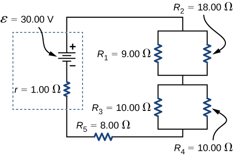
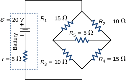
Consider the circuit below. The battery has an emf of [latex]\epsilon =30.00\phantom{\rule{0.2em}{0ex}}\text{V}[/latex] and an internal resistance of [latex]r=1.00\phantom{\rule{0.2em}{0ex}}\text{Ω}.[/latex] (a) Find the equivalent resistance of the circuit and the current out of the battery. (b) Find the current through each resistor. (c) Find the potential drop across each resistor. (d) Find the power dissipated by each resistor. (e) Find the total power supplied by the batteries.
Show Solution
a. [latex]{R}_{\text{eq}}=20.00\phantom{\rule{0.2em}{0ex}}\text{Ω}[/latex];
b. [latex]{I}_{r}=1.50\phantom{\rule{0.2em}{0ex}}\text{A},{I}_{1}=1.00\phantom{\rule{0.2em}{0ex}}\text{A},{I}_{2}=0.50\phantom{\rule{0.2em}{0ex}}\text{A},{I}_{3}=0.75\phantom{\rule{0.2em}{0ex}}\text{A},{I}_{4}=0.75\phantom{\rule{0.2em}{0ex}}\text{A},{I}_{5}=1.50\phantom{\rule{0.2em}{0ex}}\text{A}[/latex];
c. [latex]{V}_{r}=1.50\phantom{\rule{0.2em}{0ex}}\text{V},{V}_{1}=9.00\phantom{\rule{0.2em}{0ex}}\text{V},{V}_{2}=9.00\phantom{\rule{0.2em}{0ex}}\text{V},{V}_{3}=7.50\phantom{\rule{0.2em}{0ex}}\text{V},{V}_{4}=7.50\phantom{\rule{0.2em}{0ex}}\text{V},{V}_{5}=12.00\phantom{\rule{0.2em}{0ex}}\text{V}[/latex];
d. [latex]{P}_{r}=2.25\phantom{\rule{0.2em}{0ex}}\text{W},{P}_{1}=9.00\phantom{\rule{0.2em}{0ex}}\text{W},{P}_{2}=4.50\phantom{\rule{0.2em}{0ex}}\text{W},{P}_{3}=5.625\phantom{\rule{0.2em}{0ex}}\text{W},{P}_{4}=5.625\phantom{\rule{0.2em}{0ex}}\text{W},{P}_{5}=18.00\phantom{\rule{0.2em}{0ex}}\text{W}[/latex];
e. [latex]P=45.00\phantom{\rule{0.2em}{0ex}}\text{W}[/latex]
A homemade capacitor is constructed of 2 sheets of aluminum foil with an area of 2.00 square meters, separated by paper, 0.05 mm thick, of the same area and a dielectric constant of 3.7. The homemade capacitor is connected in series with a [latex]100.00\text{-}\text{Ω}[/latex] resistor, a switch, and a 6.00-V voltage source. (a) What is the RC time constant of the circuit? (b) What is the initial current through the circuit, when the switch is closed? (c) How long does it take the current to reach one third of its initial value?
A student makes a homemade resistor from a graphite pencil 5.00 cm long, where the graphite is 0.05 mm in diameter. The resistivity of the graphite is [latex]\rho =1.38\phantom{\rule{0.2em}{0ex}}×\phantom{\rule{0.2em}{0ex}}{10}^{-5}\phantom{\rule{0.2em}{0ex}}\text{Ω}\text{/}\text{m}[/latex]. The homemade resistor is place in series with a switch, a 10.00-mF capacitor and a 0.50-V power source. (a) What is the RC time constant of the circuit? (b) What is the potential drop across the pencil 1.00 s after the switch is closed?
Show Solution
a. [latex]\tau =\left(1.38\phantom{\rule{0.2em}{0ex}}×\phantom{\rule{0.2em}{0ex}}{10}^{-5}\text{Ω}\text{m}\left(\frac{5.00\phantom{\rule{0.2em}{0ex}}×\phantom{\rule{0.2em}{0ex}}{10}^{-2}\phantom{\rule{0.2em}{0ex}}\text{m}}{3.14{\left(\frac{0.05\phantom{\rule{0.2em}{0ex}}×\phantom{\rule{0.2em}{0ex}}{10}^{-3}}{2}\right)}^{2}}\right)\right)10\phantom{\rule{0.2em}{0ex}}×\phantom{\rule{0.2em}{0ex}}{10}^{-3}\phantom{\rule{0.2em}{0ex}}\text{F}=3.52\phantom{\rule{0.2em}{0ex}}\text{s}[/latex]; b. [latex]V=0.017\phantom{\rule{0.2em}{0ex}}\text{A}\left({e}^{-\frac{1.00\phantom{\rule{0.2em}{0ex}}\text{s}}{3.52\phantom{\rule{0.2em}{0ex}}\text{s}}}\right)351.59\phantom{\rule{0.2em}{0ex}}\text{Ω}=0.122\phantom{\rule{0.2em}{0ex}}\text{V}[/latex]
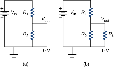
The rather simple circuit shown below is known as a voltage divider. The symbol consisting of three horizontal lines is represents “ground” and can be defined as the point where the potential is zero. The voltage divider is widely used in circuits and a single voltage source can be used to provide reduced voltage to a load resistor as shown in the second part of the figure. (a) What is the output voltage [latex]{V}_{\text{out}}[/latex] of circuit (a) in terms of [latex]{R}_{1},{R}_{2},\phantom{\rule{0.2em}{0ex}}\text{and}\phantom{\rule{0.2em}{0ex}}{V}_{\text{in}}?[/latex] (b) What is the output voltage [latex]{V}_{\text{out}}[/latex] of circuit (b) in terms of [latex]{R}_{1},{R}_{2},{R}_{L},\phantom{\rule{0.2em}{0ex}}\text{and}\phantom{\rule{0.2em}{0ex}}{V}_{\text{in}}?[/latex]
Three [latex]300\text{-}\text{Ω}[/latex] resistors are connect in series with an AAA battery with a rating of 3 AmpHours. (a) How long can the battery supply the resistors with power? (b) If the resistors are connected in parallel, how long can the battery last?
Show Solution
a. [latex]t=\frac{3\phantom{\rule{0.2em}{0ex}}\text{A}·\text{h}}{\frac{1.5\phantom{\rule{0.2em}{0ex}}\text{V}}{900\phantom{\rule{0.2em}{0ex}}\text{Ω}}}=1800\phantom{\rule{0.2em}{0ex}}\text{h}[/latex]; b. [latex]t=\frac{3\phantom{\rule{0.2em}{0ex}}\text{A}·\text{h}}{\frac{1.5\phantom{\rule{0.2em}{0ex}}\text{V}}{100\phantom{\rule{0.2em}{0ex}}\text{Ω}}}=200\phantom{\rule{0.2em}{0ex}}\text{h}[/latex]
Consider a circuit that consists of a real battery with an emf [latex]\epsilon[/latex] and an internal resistance of r connected to a variable resistor R. (a) In order for the terminal voltage of the battery to be equal to the emf of the battery, what should the resistance of the variable resistor be adjusted to? (b) In order to get the maximum current from the battery, what should the resistance variable resistor be adjusted to? (c) In order for the maximum power output of the battery to be reached, what should the resistance of the variable resistor be set to?
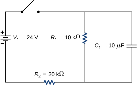
Consider the circuit shown below. What is the energy stored in each capacitor after the switch has been closed for a very long time?
Show Solution
[latex]{U}_{1}={C}_{1}{V}_{1}^{2}=0.72\text{J},\phantom{\rule{0.5em}{0ex}}{U}_{2}={C}_{2}{V}_{2}^{2}=0.338\phantom{\rule{0.2em}{0ex}}\text{J}[/latex]
Consider a circuit consisting of a battery with an emf [latex]\epsilon[/latex] and an internal resistance of r connected in series with a resistor R and a capacitor C. Show that the total energy supplied by the battery while charging the battery is equal to [latex]{\epsilon }^{2}C[/latex].
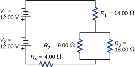
Consider the circuit shown below. The terminal voltages of the batteries are shown. (a) Find the equivalent resistance of the circuit and the current out of the battery. (b) Find the current through each resistor. (c) Find the potential drop across each resistor. (d) Find the power dissipated by each resistor. (e) Find the total power supplied by the batteries.
Show Solution
a. [latex]{R}_{\text{eq}}=24.00\phantom{\rule{0.2em}{0ex}}\text{Ω}[/latex]; b. [latex]{I}_{1}=1.00\phantom{\rule{0.2em}{0ex}}\text{A},{I}_{2}=0.67\phantom{\rule{0.2em}{0ex}}\text{A},{I}_{3}=0.33\phantom{\rule{0.2em}{0ex}}\text{A},{I}_{4}=1.00\phantom{\rule{0.2em}{0ex}}\text{A}[/latex];
c. [latex]{V}_{1}=14.00\phantom{\rule{0.2em}{0ex}}\text{V},{V}_{2}=6.00\phantom{\rule{0.2em}{0ex}}\text{V},{V}_{3}=6.00\phantom{\rule{0.2em}{0ex}}\text{V},{V}_{4}=4.00\phantom{\rule{0.2em}{0ex}}\text{V}[/latex];
d. [latex]{P}_{1}=14.00\phantom{\rule{0.2em}{0ex}}\text{W},{P}_{2}=4.04\phantom{\rule{0.2em}{0ex}}\text{W},{P}_{3}=1.96\phantom{\rule{0.2em}{0ex}}\text{W},{P}_{4}=4.00\phantom{\rule{0.2em}{0ex}}\text{W}[/latex]; e. [latex]P=24.00\phantom{\rule{0.2em}{0ex}}\text{W}[/latex]
Consider the circuit shown below. (a) What is the terminal voltage of the battery? (b) What is the potential drop across resistor [latex]{R}_{2}[/latex]?
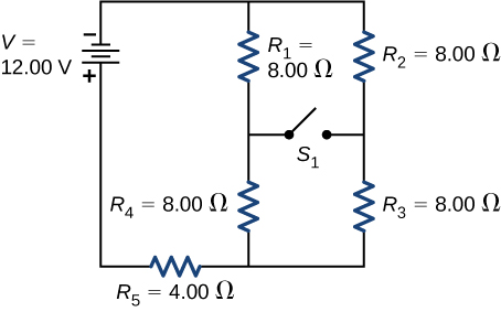
Consider the circuit shown below. (a)Determine the equivalent resistance and the current from the battery with switch [latex]{S}_{1}[/latex] open. (b) Determine the equivalent resistance and the current from the battery with switch [latex]{S}_{1}[/latex] closed.
Show Solution
a. [latex]{R}_{\text{eq}}=12.00\phantom{\rule{0.2em}{0ex}}\text{Ω},I=1.00\phantom{\rule{0.2em}{0ex}}\text{A}[/latex]; b. [latex]{R}_{\text{eq}}=12.00\phantom{\rule{0.2em}{0ex}}\text{Ω},I=1.00\phantom{\rule{0.2em}{0ex}}\text{A}[/latex]
Two resistors, one having a resistance of [latex]145\phantom{\rule{0.2em}{0ex}}\text{Ω}[/latex], are connected in parallel to produce a total resistance of [latex]150\phantom{\rule{0.2em}{0ex}}\text{Ω}[/latex]. (a) What is the value of the second resistance? (b) What is unreasonable about this result? (c) Which assumptions are unreasonable or inconsistent?
Two resistors, one having a resistance of [latex]900\phantom{\rule{0.2em}{0ex}}\text{k}\text{Ω},[/latex] are connected in series to produce a total resistance of [latex]0.500\phantom{\rule{0.2em}{0ex}}\text{M}\text{Ω}[/latex]. (a) What is the value of the second resistance? (b) What is unreasonable about this result? (c) Which assumptions are unreasonable or inconsistent?
Show Solution
a. [latex]-400\phantom{\rule{0.2em}{0ex}}\text{k}\text{Ω}[/latex]; b. You cannot have negative resistance. c. The assumption that [latex]{R}_{\text{eq}}<{R}_{1}[/latex] is unreasonable. Series resistance is always greater than any of the individual resistances.</p>
Apply the junction rule at point a shown below.
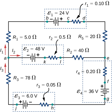
Apply the loop rule to Loop akledcba in the preceding problem.
Show Solution
[latex]{E}_{2}-{I}_{2}{r}_{2}-{I}_{2}{R}_{2}+{I}_{1}{R}_{5}+{I}_{1}{r}_{1}-{E}_{1}+{I}_{1}{R}_{1}=0[/latex]
Find the currents flowing in the circuit in the preceding problem. Explicitly show how you follow the steps in the Problem-Solving Strategy: Series and Parallel Resistors.
Consider the circuit shown below. (a) Find the current through each resistor. (b) Check the calculations by analyzing the power in the circuit.
Show Solution
a. [latex]I=1.17\phantom{\rule{0.2em}{0ex}}\text{A},{I}_{1}=0.50\phantom{\rule{0.2em}{0ex}}\text{A},{I}_{2}=0.67\phantom{\rule{0.2em}{0ex}}\text{A},{I}_{3}=0.67\phantom{\rule{0.2em}{0ex}}\text{A},{I}_{4}=0.50\phantom{\rule{0.2em}{0ex}}\text{A},{I}_{5}=0.17\phantom{\rule{0.2em}{0ex}}\text{A}[/latex];
b. [latex]{P}_{\text{output}}=23.4\phantom{\rule{0.2em}{0ex}}\text{W},{P}_{\text{input}}=23.4\phantom{\rule{0.2em}{0ex}}\text{W}[/latex]
A flashing lamp in a Christmas earring is based on an RC discharge of a capacitor through its resistance. The effective duration of the flash is 0.250 s, during which it produces an average 0.500 W from an average 3.00 V. (a) What energy does it dissipate? (b) How much charge moves through the lamp? (c) Find the capacitance. (d) What is the resistance of the lamp? (Since average values are given for some quantities, the shape of the pulse profile is not needed.)
A [latex]160\text{-}\mu \text{F}[/latex] capacitor charged to 450 V is discharged through a [latex]31.2\text{-k}\text{Ω}[/latex] resistor. (a) Find the time constant. (b) Calculate the temperature increase of the resistor, given that its mass is 2.50 g and its specific heat is [latex]1.67\phantom{\rule{0.2em}{0ex}}\text{kJ/kg}·\text{°}\text{C},[/latex] noting that most of the thermal energy is retained in the short time of the discharge. (c) Calculate the new resistance, assuming it is pure carbon. (d) Does this change in resistance seem significant?
Show Solution
a. 4.99 s; b. [latex]3.87\phantom{\rule{0.2em}{0ex}}\text{°C}[/latex]; c. [latex]3.11\phantom{\rule{0.2em}{0ex}}×\phantom{\rule{0.2em}{0ex}}{10}^{4}\phantom{\rule{0.2em}{0ex}}\text{Ω}[/latex]; d. No, this change does not seem significant. It probably would not be noticed.
Challenge Problems
Some camera flashes use flash tubes that require a high voltage. They obtain a high voltage by charging capacitors in parallel and then internally changing the connections of the capacitors to place them in series. Consider a circuit that uses four AAA batteries connected in series to charge six 10-mF capacitors through an equivalent resistance of [latex]100\phantom{\rule{0.2em}{0ex}}\text{Ω}[/latex]. The connections are then switched internally to place the capacitors in series. The capacitors discharge through a lamp with a resistance of [latex]100\phantom{\rule{0.2em}{0ex}}\text{Ω}[/latex]. (a) What is the RC time constant and the initial current out of the batteries while they are connected in parallel? (b) How long does it take for the capacitors to charge to [latex]90%[/latex] of the terminal voltages of the batteries? (c) What is the RC time constant and the initial current of the capacitors connected in series assuming it discharges at [latex]90%[/latex] of full charge? (d) How long does it take the current to decrease to [latex]10%[/latex] of the initial value?
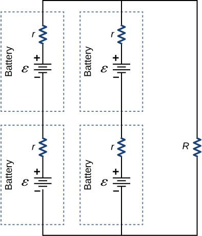
Consider the circuit shown below. Each battery has an emf of 1.50 V and an internal resistance of [latex]1.00\phantom{\rule{0.2em}{0ex}}\text{Ω}.[/latex] (a) What is the current through the external resistor, which has a resistance of 10.00 ohms? (b) What is the terminal voltage of each battery?
Show Solution
a. 0.273 A; b. [latex]{V}_{T}=1.36\phantom{\rule{0.2em}{0ex}}\text{V}[/latex]
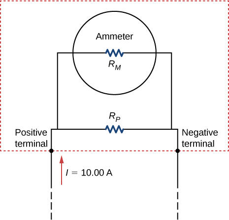
Analog meters use a galvanometer, which essentially consists of a coil of wire with a small resistance and a pointer with a scale attached. When current runs through the coil, the pointer turns; the amount the pointer turns is proportional to the amount of current running through the coil. Galvanometers can be used to make an ammeter if a resistor is placed in parallel with the galvanometer. Consider a galvanometer that has a resistance of [latex]25.00\phantom{\rule{0.2em}{0ex}}\text{Ω}[/latex] and gives a full scale reading when a [latex]50\text{-}\mu \text{A}[/latex] current runs through it. The galvanometer is to be used to make an ammeter that has a full scale reading of 10.00 A, as shown below. Recall that an ammeter is connected in series with the circuit of interest, so all 10 A must run through the meter. (a) What is the current through the parallel resistor in the meter? (b) What is the voltage across the parallel resistor? (c) What is the resistance of the series resistor?
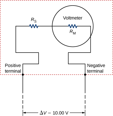
Analog meters use a galvanometer, which essentially consists of a coil of wire with a small resistance and a pointer with a scale attached. When current runs through the coil, the point turns; the amount the pointer turns is proportional to the amount of current running through the coil. Galvanometers can be used to make a voltmeter if a resistor is placed in series with the galvanometer. Consider a galvanometer that has a resistance of [latex]25.00\phantom{\rule{0.2em}{0ex}}\text{Ω}[/latex] and gives a full scale reading when a [latex]50\text{-}\mu \text{A}[/latex] current runs through it. The galvanometer is to be used to make an voltmeter that has a full scale reading of 10.00 V, as shown below. Recall that a voltmeter is connected in parallel with the component of interest, so the meter must have a high resistance or it will change the current running through the component. (a) What is the potential drop across the series resistor in the meter? (b) What is the resistance of the parallel resistor?
Show Solution
a. [latex]{V}_{s}=V-{I}_{M}{R}_{M}=9.99875\phantom{\rule{0.2em}{0ex}}\text{V}[/latex]; b. [latex]{R}_{S}=\frac{{V}_{P}}{{I}_{M}}=199.975\phantom{\rule{0.2em}{0ex}}\text{k}\text{Ω}[/latex]
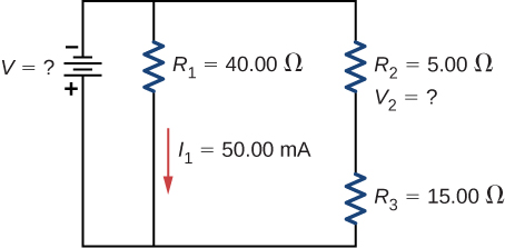
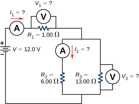
Consider the circuit shown below. Find [latex]{I}_{1},{V}_{1},{I}_{2},\phantom{\rule{0.2em}{0ex}}\text{and}\phantom{\rule{0.2em}{0ex}}{V}_{3}.[/latex]
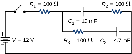
Consider the circuit below. (a) What is the RC time constant of the circuit? (b) What is the initial current in the circuit once the switch is closed? (c) How much time passes between the instant the switch is closed and the time the current has reached half of the initial current?

Show Solution
a. [latex]\tau =3800\phantom{\rule{0.2em}{0ex}}\text{s}[/latex]; b. 1.26 mA; c. [latex]t=2633.96\phantom{\rule{0.2em}{0ex}}\text{s}[/latex]
Consider the circuit below. (a) What is the initial current through resistor [latex]{R}_{2}[/latex] when the switch is closed? (b) What is the current through resistor [latex]{R}_{2}[/latex] when the capacitor is fully charged, long after the switch is closed? (c) What happens if the switch is opened after it has been closed for some time? (d) If the switch has been closed for a time period long enough for the capacitor to become fully charged, and then the switch is opened, how long before the current through resistor [latex]{R}_{1}[/latex] reaches half of its initial value?
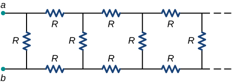
Consider the infinitely long chain of resistors shown below. What is the resistance between terminals a and b?
Show Solution
[latex]{R}_{\text{eq}}=\left(\sqrt{3}–1\right)R[/latex]
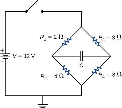
Consider the circuit below. The capacitor has a capacitance of 10 mF. The switch is closed and after a long time the capacitor is fully charged. (a) What is the current through each resistor a long time after the switch is closed? (b) What is the voltage across each resistor a long time after the switch is closed? (c) What is the voltage across the capacitor a long time after the switch is closed? (d) What is the charge on the capacitor a long time after the switch is closed? (e) The switch is then opened. The capacitor discharges through the resistors. How long from the time before the current drops to one fifth of the initial value?
A 120-V immersion heater consists of a coil of wire that is placed in a cup to boil the water. The heater can boil one cup of [latex]20.00\phantom{\rule{0.2em}{0ex}}\text{°}\text{C}[/latex] water in 180.00 seconds. You buy one to use in your dorm room, but you are worried that you will overload the circuit and trip the 15.00-A, 120-V circuit breaker, which supplies your dorm room. In your dorm room, you have four 100.00-W incandescent lamps and a 1500.00-W space heater. (a) What is the power rating of the immersion heater? (b) Will it trip the breaker when everything is turned on? (c) If it you replace the incandescent bulbs with 18.00-W LED, will the breaker trip when everything is turned on?
Show Solution
a. [latex]{P}_{\text{imheater}}=\frac{1\text{cup}\left(\frac{0.000237\phantom{\rule{0.2em}{0ex}}{\text{m}}^{3}}{\text{cup}}\right)\left(\frac{1000\phantom{\rule{0.2em}{0ex}}\text{kg}}{{\text{m}}^{3}}\right)\left(4186\frac{\text{J}}{\text{kg °C}}\right)\left(100\phantom{\rule{0.2em}{0ex}}\text{°}\text{C}-20\phantom{\rule{0.2em}{0ex}}\text{°}\text{C}\right)}{180.00\phantom{\rule{0.2em}{0ex}}\text{s}}\approx 441\phantom{\rule{0.2em}{0ex}}\text{W}[/latex];
b. [latex]I=\frac{441\phantom{\rule{0.2em}{0ex}}\text{W}}{120\phantom{\rule{0.2em}{0ex}}\text{V}}+4\left(\frac{100\phantom{\rule{0.2em}{0ex}}\text{W}}{120\phantom{\rule{0.2em}{0ex}}\text{V}}\right)+\frac{1500\phantom{\rule{0.2em}{0ex}}\text{W}}{120\phantom{\rule{0.2em}{0ex}}\text{V}}=19.51\phantom{\rule{0.2em}{0ex}}\text{A}[/latex]; Yes, the breaker will trip.
c. [latex]I=\frac{441\phantom{\rule{0.2em}{0ex}}\text{W}}{120\phantom{\rule{0.2em}{0ex}}\text{V}}+4\left(\frac{18\phantom{\rule{0.2em}{0ex}}\text{W}}{120\phantom{\rule{0.2em}{0ex}}\text{V}}\right)+\frac{1500\phantom{\rule{0.2em}{0ex}}\text{W}}{120\phantom{\rule{0.2em}{0ex}}\text{V}}=16.78\phantom{\rule{0.2em}{0ex}}\text{A}[/latex]; Yes, the breaker will trip.
Find the resistance that must be placed in series with a [latex]25.0\text{-}\text{Ω}[/latex] galvanometer having a [latex]50.0\text{-}\mu \text{A}[/latex] sensitivity (the same as the one discussed in the text) to allow it to be used as a voltmeter with a 3000-V full-scale reading. Include a circuit diagram with your solution.
Find the resistance that must be placed in parallel with a [latex]60.0\text{-}\text{Ω}[/latex] galvanometer having a 1.00-mA sensitivity (the same as the one discussed in the text) to allow it to be used as an ammeter with a 25.0-A full-scale reading. Include a circuit diagram with your solution.
Show Solution
,
[latex]2.40\phantom{\rule{0.2em}{0ex}}×\phantom{\rule{0.2em}{0ex}}{10}^{-3}\phantom{\rule{0.2em}{0ex}}\text{Ω}[/latex]
Glossary
- shock hazard
- hazard in which an electric current passes through a person
- thermal hazard
- hazard in which an excessive electric current causes undesired thermal effects
- three-wire system
- wiring system used at present for safety reasons, with live, neutral, and ground wires
Licenses and Attributions
Household Wiring and Electrical Safety. Authored by: OpenStax College. Located at: https://openstax.org/books/university-physics-volume-2/pages/10-6-household-wiring-and-electrical-safety. License: CC BY: Attribution. License Terms: Download for free at https://openstax.org/books/university-physics-volume-2/pages/1-introduction
