
Chapter 13. Electromagnetic Induction
13.6 Electric Generators and Back Emf
Learning Objectives
By the end of this section, you will be able to:
- Explain how an electric generator works
- Determine the induced emf in a loop at any time interval, rotating at a constant rate in a magnetic field
- Show that rotating coils have an induced emf; in motors this is called back emf because it opposes the emf input to the motor
A variety of important phenomena and devices can be understood with Faraday’s law. In this section, we examine two of these.
Electric Generators
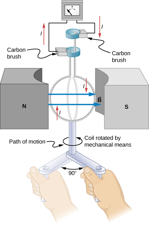
Electric generators induce an emf by rotating a coil in a magnetic field, as briefly discussed in Motional Emf. We now explore generators in more detail. Consider the following example.
Example
Calculating the Emf Induced in a Generator Coil
The generator coil shown in Figure 13.27 is rotated through one-fourth of a revolution (from [latex]\theta =0\text{°}[/latex] to[latex]\theta =90\text{°}[/latex]) in 15.0 ms. The 200-turn circular coil has a 5.00-cm radius and is in a uniform 0.80-T magnetic field. What is the emf induced?
Strategy
Faraday’s law of induction is used to find the emf induced:
We recognize this situation as the same one in Example 13.6. According to the diagram, the projection of the surface normal vector [latex]\hat{\textbf{n}}[/latex] to the magnetic field is initially[latex]\text{cos}\phantom{\rule{0.2em}{0ex}}\theta ,[/latex] and this is inserted by the definition of the dot product. The magnitude of the magnetic field and area of the loop are fixed over time, which makes the integration simplify quickly. The induced emf is written out using Faraday’s law:
Solution
Show Answer
We are given that [latex]N=200,[/latex] [latex]B=0.80\phantom{\rule{0.2em}{0ex}}\text{T},[/latex] [latex]\theta =90\text{°}[/latex], [latex]d\theta =90\text{°}=\pi \text{/}2[/latex], and [latex]dt=15.0\phantom{\rule{0.2em}{0ex}}\text{ms}.[/latex] The area of the loop is
Entering this value gives
Significance
This is a practical average value, similar to the 120 V used in household power.
The emf calculated in Example 13.9 is the average over one-fourth of a revolution. What is the emf at any given instant? It varies with the angle between the magnetic field and a perpendicular to the coil. We can get an expression for emf as a function of time by considering the motional emf on a rotating rectangular coil of width w and height l in a uniform magnetic field, as illustrated in Figure 13.28.
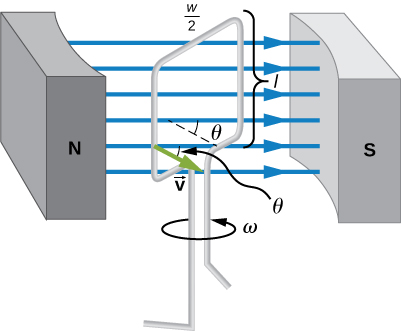
Charges in the wires of the loop experience the magnetic force, because they are moving in a magnetic field. Charges in the vertical wires experience forces parallel to the wire, causing currents. But those in the top and bottom segments feel a force perpendicular to the wire, which does not cause a current. We can thus find the induced emf by considering only the side wires. Motional emf is given to be [latex]\epsilon =Blv[/latex], where the velocity v is perpendicular to the magnetic field B. Here the velocity is at an angle [latex]\theta[/latex] with B, so that its component perpendicular to B is v sin [latex]\theta[/latex] (see Figure 13.28). Thus, in this case, the emf induced on each side is [latex]\epsilon =Blv\phantom{\rule{0.2em}{0ex}}\text{sin}\phantom{\rule{0.2em}{0ex}}\theta[/latex], and they are in the same direction. The total emf around the loop is then
This expression is valid, but it does not give emf as a function of time. To find the time dependence of emf, we assume the coil rotates at a constant angular velocity [latex]\omega[/latex]. The angle [latex]\theta[/latex] is related to angular velocity by [latex]\theta =\omega t,[/latex] so that
Now, linear velocity v is related to angular velocity [latex]\omega[/latex] by [latex]v=r\omega .[/latex] Here, [latex]r=w\text{/}2,[/latex] so that [latex]v=\left(w\text{/}2\right)\omega ,[/latex] and
Noting that the area of the loop is [latex]A=lw,[/latex] and allowing for N loops, we find that
This is the emf induced in a generator coil of N turns and area A rotating at a constant angular velocity [latex]\omega[/latex] in a uniform magnetic field B. This can also be expressed as
where
is the peak emf, since the maximum value of [latex]\mathrm{sin}\left(wt\right)=1[/latex]. Note that the frequency of the oscillation is [latex]f=\omega \text{/}2\pi[/latex] and the period is [latex]T=\text{1/}f=2\pi \text{/}\phantom{\rule{0.2em}{0ex}}\omega .[/latex] Figure 13.29 shows a graph of emf as a function of time, and it now seems reasonable that ac voltage is sinusoidal.
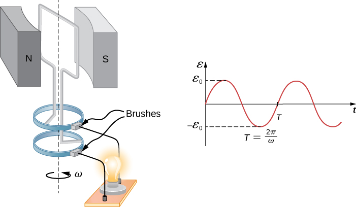
The fact that the peak emf is [latex]{\epsilon }_{0}=NBA\omega[/latex] makes good sense. The greater the number of coils, the larger their area, and the stronger the field, the greater the output voltage. It is interesting that the faster the generator is spun (greater [latex]\omega[/latex]), the greater the emf. This is noticeable on bicycle generators—at least the cheaper varieties.
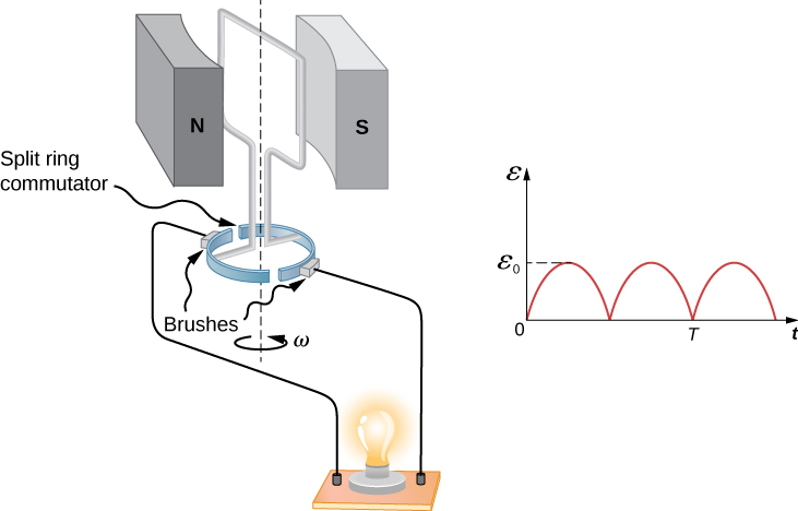
Figure 13.30 shows a scheme by which a generator can be made to produce pulsed dc. More elaborate arrangements of multiple coils and split rings can produce smoother dc, although electronic rather than mechanical means are usually used to make ripple-free dc.
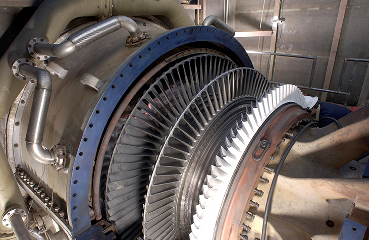
In real life, electric generators look a lot different from the figures in this section, but the principles are the same. The source of mechanical energy that turns the coil can be falling water (hydropower), steam produced by the burning of fossil fuels, or the kinetic energy of wind. Figure 13.31 shows a cutaway view of a steam turbine; steam moves over the blades connected to the shaft, which rotates the coil within the generator. The generation of electrical energy from mechanical energy is the basic principle of all power that is sent through our electrical grids to our homes.
Generators illustrated in this section look very much like the motors illustrated previously. This is not coincidental. In fact, a motor becomes a generator when its shaft rotates. Certain early automobiles used their starter motor as a generator. In the next section, we further explore the action of a motor as a generator.
Back Emf
Generators convert mechanical energy into electrical energy, whereas motors convert electrical energy into mechanical energy. Thus, it is not surprising that motors and generators have the same general construction. A motor works by sending a current through a loop of wire located in a magnetic field. As a result, the magnetic field exerts torque on the loop. This rotates a shaft, thereby extracting mechanical work out of the electrical current sent in initially. (Refer to Force and Torque on a Current Loop for a discussion on motors that will help you understand more about them before proceeding.)
When the coil of a motor is turned, magnetic flux changes through the coil, and an emf (consistent with Faraday’s law) is induced. The motor thus acts as a generator whenever its coil rotates. This happens whether the shaft is turned by an external input, like a belt drive, or by the action of the motor itself. That is, when a motor is doing work and its shaft is turning, an emf is generated. Lenz’s law tells us the emf opposes any change, so that the input emf that powers the motor is opposed by the motor’s self-generated emf, called the back emf of the motor (Figure 13.32).
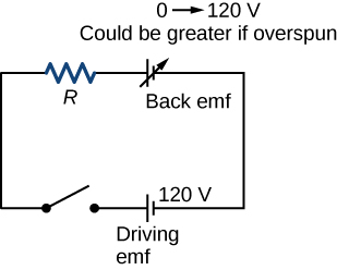
The generator output of a motor is the difference between the supply voltage and the back emf. The back emf is zero when the motor is first turned on, meaning that the coil receives the full driving voltage and the motor draws maximum current when it is on but not turning. As the motor turns faster, the back emf grows, always opposing the driving emf, and reduces both the voltage across the coil and the amount of current it draws. This effect is noticeable in many common situations. When a vacuum cleaner, refrigerator, or washing machine is first turned on, lights in the same circuit dim briefly due to the IR drop produced in feeder lines by the large current drawn by the motor.
When a motor first comes on, it draws more current than when it runs at its normal operating speed. When a mechanical load is placed on the motor, like an electric wheelchair going up a hill, the motor slows, the back emf drops, more current flows, and more work can be done. If the motor runs at too low a speed, the larger current can overheat it (via resistive power in the coil, [latex]P={I}^{2}R[/latex]), perhaps even burning it out. On the other hand, if there is no mechanical load on the motor, it increases its angular velocity [latex]\omega[/latex] until the back emf is nearly equal to the driving emf. Then the motor uses only enough energy to overcome friction.
Eddy currents in iron cores of motors can cause troublesome energy losses. These are usually minimized by constructing the cores out of thin, electrically insulated sheets of iron. The magnetic properties of the core are hardly affected by the lamination of the insulating sheet, while the resistive heating is reduced considerably. Consider, for example, the motor coils represented in Figure 13.32. The coils have an equivalent resistance of [latex]0.400\phantom{\rule{0.2em}{0ex}}\text{Ω}[/latex] and are driven by an emf of 48.0 V. Shortly after being turned on, they draw a current
and thus dissipate [latex]P={I}^{2}R=5.76\phantom{\rule{0.2em}{0ex}}\text{kW}[/latex] of energy as heat transfer. Under normal operating conditions for this motor, suppose the back emf is 40.0 V. Then at operating speed, the total voltage across the coils is 8.0 V (48.0 V minus the 40.0 V back emf), and the current drawn is
Under normal load, then, the power dissipated is [latex]P=IV=\left(20\phantom{\rule{0.2em}{0ex}}\text{A}\right)\left(8.0\phantom{\rule{0.2em}{0ex}}\text{V}\right)=160\phantom{\rule{0.2em}{0ex}}\text{W}.[/latex] This does not cause a problem for this motor, whereas the former 5.76 kW would burn out the coils if sustained.
Example
A Series-Wound Motor in Operation
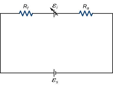
The total resistance [latex]\left({R}_{f}+{R}_{a}\right)[/latex] of a series-wound dc motor is [latex]2.0\phantom{\rule{0.2em}{0ex}}\text{Ω}[/latex] (Figure 13.33). When connected to a 120-V source ([latex]{\epsilon }_{S}[/latex]), the motor draws 10 A while running at constant angular velocity. (a) What is the back emf induced in the rotating coil, [latex]{\epsilon }_{i}?[/latex] (b) What is the mechanical power output of the motor? (c) How much power is dissipated in the resistance of the coils? (d) What is the power output of the 120-V source? (e) Suppose the load on the motor increases, causing it to slow down to the point where it draws 20 A. Answer parts (a) through (d) for this situation.
Strategy
The back emf is calculated based on the difference between the supplied voltage and the loss from the current through the resistance. The power from each device is calculated from one of the power formulas based on the given information.
Solution
Show Answer
- The back emf is
[latex]{\epsilon }_{i}={\epsilon }_{s}-I\left({R}_{f}+{R}_{a}\right)=120\phantom{\rule{0.2em}{0ex}}\text{V}-\left(10\phantom{\rule{0.2em}{0ex}}\text{A}\right)\left(2.0\phantom{\rule{0.2em}{0ex}}\text{Ω}\right)=100\phantom{\rule{0.2em}{0ex}}\text{V}\text{.}[/latex] - Since the potential across the armature is 100 V when the current through it is 10 A, the power output of the motor is
[latex]{P}_{\text{m}}={\epsilon }_{i}I=\left(100\phantom{\rule{0.2em}{0ex}}\text{V}\right)\left(10\phantom{\rule{0.2em}{0ex}}\text{A}\right)=1.0\phantom{\rule{0.2em}{0ex}}×\phantom{\rule{0.2em}{0ex}}{10}^{3}\phantom{\rule{0.2em}{0ex}}\text{W}\text{.}[/latex] - A 10-A current flows through coils whose combined resistance is [latex]2.0\phantom{\rule{0.2em}{0ex}}\text{Ω}[/latex], so the power dissipated in the coils is
[latex]{P}_{R}={I}^{2}R={\left(10\phantom{\rule{0.2em}{0ex}}\text{A}\right)}^{2}\left(2.0\phantom{\rule{0.2em}{0ex}}\text{Ω}\right)=2.0\phantom{\rule{0.2em}{0ex}}×\phantom{\rule{0.2em}{0ex}}{10}^{2}\phantom{\rule{0.2em}{0ex}}\text{W}\text{.}[/latex] - Since 10 A is drawn from the 120-V source, its power output is
[latex]{P}_{s}={\epsilon }_{s}\phantom{\rule{0.2em}{0ex}}I=\left(120\phantom{\rule{0.2em}{0ex}}\text{V}\right)\left(10\phantom{\rule{0.2em}{0ex}}\text{A}\right)=1.2\phantom{\rule{0.2em}{0ex}}×\phantom{\rule{0.2em}{0ex}}{10}^{3}\phantom{\rule{0.2em}{0ex}}\text{W}\text{.}[/latex] - Repeating the same calculations with [latex]I=20\phantom{\rule{0.2em}{0ex}}\text{A}[/latex], we find
[latex]{\epsilon }_{\text{i}}=\phantom{\rule{0.2em}{0ex}}80\phantom{\rule{0.2em}{0ex}}\text{V},{P}_{\text{m}}=\phantom{\rule{0.2em}{0ex}}1.6\phantom{\rule{0.2em}{0ex}}×\phantom{\rule{0.2em}{0ex}}1{0}^{3}\phantom{\rule{0.2em}{0ex}}\text{W},{P}_{R}=8.0\phantom{\rule{0.2em}{0ex}}×\phantom{\rule{0.2em}{0ex}}{10}^{2}\phantom{\rule{0.2em}{0ex}}\text{W},\phantom{\rule{0.2em}{0ex}}\text{and}\phantom{\rule{0.2em}{0ex}}{P}_{s}=2.4\phantom{\rule{0.2em}{0ex}}×\phantom{\rule{0.2em}{0ex}}{10}^{3}\phantom{\rule{0.2em}{0ex}}\text{W}.[/latex]
The motor is turning more slowly in this case, so its power output and the power of the source are larger.
Significance
Notice that we have an energy balance in part (d): [latex]1.2\phantom{\rule{0.2em}{0ex}}×\phantom{\rule{0.2em}{0ex}}{10}^{3}\phantom{\rule{0.2em}{0ex}}\text{W}=1.0\phantom{\rule{0.2em}{0ex}}×\phantom{\rule{0.2em}{0ex}}{10}^{3}\phantom{\rule{0.2em}{0ex}}\text{W}+2.0\phantom{\rule{0.2em}{0ex}}×\phantom{\rule{0.2em}{0ex}}{10}^{2}\phantom{\rule{0.2em}{0ex}}\text{W}.[/latex]
Summary
- An electric generator rotates a coil in a magnetic field, inducing an emf given as a function of time by [latex]\epsilon =NBA\omega \phantom{\rule{0.2em}{0ex}}\text{sin}\left(\omega t\right)[/latex] where A is the area of an N-turn coil rotated at a constant angular velocity [latex]\omega[/latex] in a uniform magnetic field [latex]\stackrel{\to }{\textbf{B}}.[/latex]
- The peak emf of a generator is [latex]{\epsilon }_{0}=NBA\omega[/latex].
- Any rotating coil produces an induced emf. In motors, this is called back emf because it opposes the emf input to the motor.
Problems
Design a current loop that, when rotated in a uniform magnetic field of strength 0.10 T, will produce an emf [latex]\epsilon ={\epsilon }_{0}\phantom{\rule{0.2em}{0ex}}\text{sin}\phantom{\rule{0.2em}{0ex}}\omega t,[/latex] where [latex]{\epsilon }_{0}=110\phantom{\rule{0.2em}{0ex}}\text{V}[/latex] and [latex]\omega =120\pi \phantom{\rule{0.2em}{0ex}}\text{rad/s}\text{.}[/latex]
Show Solution
three turns with an area of 1 m2
A flat, square coil of 20 turns that has sides of length 15.0 cm is rotating in a magnetic field of strength 0.050 T. If the maximum emf produced in the coil is 30.0 mV, what is the angular velocity of the coil?
A 50-turn rectangular coil with dimensions [latex]0.15\phantom{\rule{0.2em}{0ex}}\text{m}\phantom{\rule{0.2em}{0ex}}×\phantom{\rule{0.2em}{0ex}}0.40\phantom{\rule{0.2em}{0ex}}\text{m}[/latex] rotates in a uniform magnetic field of magnitude 0.75 T at 3600 rev/min. (a) Determine the emf induced in the coil as a function of time. (b) If the coil is connected to a [latex]1000\text{-}\text{Ω}[/latex] resistor, what is the power as a function of time required to keep the coil turning at 3600 rpm? (c) Answer part (b) if the coil is connected to a 2000-[latex]\text{Ω}[/latex] resistor.
Show Solution
a. [latex]\begin{array}{}\\ \\ \hfill \omega & =\hfill & 120\pi \phantom{\rule{0.2em}{0ex}}\text{rad/s,}\hfill \\ \hfill \epsilon & =\hfill & 850\phantom{\rule{0.2em}{0ex}}\text{sin}\phantom{\rule{0.2em}{0ex}}120\phantom{\rule{0.2em}{0ex}}\pi \text{t V;}\hfill \end{array}[/latex]
b. [latex]P=720\phantom{\rule{0.2em}{0ex}}{\text{sin}}^{2}120\phantom{\rule{0.2em}{0ex}}\pi t\phantom{\rule{0.2em}{0ex}}\text{W;}[/latex]
c. [latex]P=360\phantom{\rule{0.2em}{0ex}}{\text{sin}}^{2}120\phantom{\rule{0.2em}{0ex}}\pi t\phantom{\rule{0.2em}{0ex}}\text{W}[/latex]
The square armature coil of an alternating current generator has 200 turns and is 20.0 cm on side. When it rotates at 3600 rpm, its peak output voltage is 120 V. (a) What is the frequency of the output voltage? (b) What is the strength of the magnetic field in which the coil is turning?
A flip coil is a relatively simple device used to measure a magnetic field. It consists of a circular coil of N turns wound with fine conducting wire. The coil is attached to a ballistic galvanometer, a device that measures the total charge that passes through it. The coil is placed in a magnetic field [latex]\stackrel{\to }{\textbf{B}}[/latex] such that its face is perpendicular to the field. It is then flipped through [latex]180\text{°},[/latex] and the total charge Q that flows through the galvanometer is measured. (a) If the total resistance of the coil and galvanometer is R, what is the relationship between B and Q? Because the coil is very small, you can assume that [latex]\stackrel{\to }{\textbf{B}}[/latex] is uniform over it. (b) How can you determine whether or not the magnetic field is perpendicular to the face of the coil?
Show Solution
a. B is proportional to Q; b. If the coin turns easily, the magnetic field is perpendicular. If the coin is at an equilibrium position, it is parallel.
The flip coil of the preceding problem has a radius of 3.0 cm and is wound with 40 turns of copper wire. The total resistance of the coil and ballistic galvanometer is [latex]0.20\phantom{\rule{0.2em}{0ex}}\text{Ω.}[/latex] When the coil is flipped through [latex]180\text{°}[/latex] in a magnetic field [latex]\stackrel{\to }{\textbf{B}},[/latex] a change of 0.090 C flows through the ballistic galvanometer. (a) Assuming that [latex]\stackrel{\to }{\textbf{B}}[/latex] and the face of the coil are initially perpendicular, what is the magnetic field? (b) If the coil is flipped through [latex]90\text{°},[/latex] what is the reading of the galvanometer?
A 120-V, series-wound motor has a field resistance of 80 [latex]\text{Ω}[/latex] and an armature resistance of 10 [latex]\text{Ω}[/latex]. When it is operating at full speed, a back emf of 75 V is generated. (a) What is the initial current drawn by the motor? When the motor is operating at full speed, where are (b) the current drawn by the motor, (c) the power output of the source, (d) the power output of the motor, and (e) the power dissipated in the two resistances?
Show Solution
a. 1.33 A; b. 0.50 A; c. 60 W; d. 37.5 W; e. 22.5W
A small series-wound dc motor is operated from a 12-V car battery. Under a normal load, the motor draws 4.0 A, and when the armature is clamped so that it cannot turn, the motor draws 24 A. What is the back emf when the motor is operating normally?
Glossary
- back emf
- emf generated by a running motor, because it consists of a coil turning in a magnetic field; it opposes the voltage powering the motor
- peak emf
- maximum emf produced by a generator
- electric generator
- device for converting mechanical work into electric energy; it induces an emf by rotating a coil in a magnetic field
Licenses and Attributions
Electric Generators and Back Emf. Authored by: OpenStax College. Located at: https://openstax.org/books/university-physics-volume-2/pages/13-6-electric-generators-and-back-emf. License: CC BY: Attribution. License Terms: Download for free at https://openstax.org/books/university-physics-volume-2/pages/1-introduction
