
Chapter 12. Sources of Magnetic Fields
12.3 Magnetic Force between Two Parallel Currents
Learning Objectives
By the end of this section, you will be able to:
- Explain how parallel wires carrying currents can attract or repel each other
- Define the ampere and describe how it is related to current-carrying wires
- Calculate the force of attraction or repulsion between two current-carrying wires
You might expect that two current-carrying wires generate significant forces between them, since ordinary currents produce magnetic fields and these fields exert significant forces on ordinary currents. But you might not expect that the force between wires is used to define the ampere. It might also surprise you to learn that this force has something to do with why large circuit breakers burn up when they attempt to interrupt large currents.
The force between two long, straight, and parallel conductors separated by a distance r can be found by applying what we have developed in the preceding sections. Figure 12.9 shows the wires, their currents, the field created by one wire, and the consequent force the other wire experiences from the created field. Let us consider the field produced by wire 1 and the force it exerts on wire 2 (call the force [latex]{F}_{2}[/latex]). The field due to [latex]{I}_{1}[/latex] at a distance r is
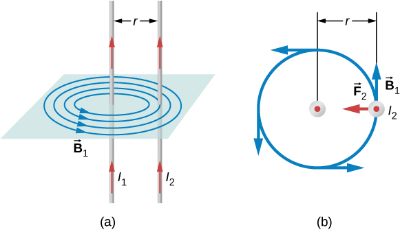
This field is uniform from the wire 1 and perpendicular to it, so the force [latex]{F}_{2}[/latex] it exerts on a length l of wire 2 is given by [latex]F=IlB\mathrm{sin}\phantom{\rule{0.1em}{0ex}}\theta[/latex] with [latex]\mathrm{sin}\phantom{\rule{0.1em}{0ex}}\theta =1\text{:}[/latex]
The forces on the wires are equal in magnitude, so we just write F for the magnitude of [latex]{F}_{2}.[/latex] (Note that [latex]{\stackrel{\to }{\textbf{F}}}_{1}=-{\stackrel{\to }{\textbf{F}}}_{2}.[/latex]) Since the wires are very long, it is convenient to think in terms of F/l, the force per unit length. Substituting the expression for [latex]{B}_{1}[/latex] into Equation 12.10 and rearranging terms gives
The ratio F/l is the force per unit length between two parallel currents [latex]{I}_{1}[/latex] and [latex]{I}_{2}[/latex] separated by a distance r. The force is attractive if the currents are in the same direction and repulsive if they are in opposite directions.
This force is responsible for the pinch effect in electric arcs and other plasmas. The force exists whether the currents are in wires or not. It is only apparent if the overall charge density is zero; otherwise, the Coulomb repulsion overwhelms the magnetic attraction. In an electric arc, where charges are moving parallel to one another, an attractive force squeezes currents into a smaller tube. In large circuit breakers, such as those used in neighborhood power distribution systems, the pinch effect can concentrate an arc between plates of a switch trying to break a large current, burn holes, and even ignite the equipment. Another example of the pinch effect is found in the solar plasma, where jets of ionized material, such as solar flares, are shaped by magnetic forces.
The definition of the ampere is based on the force between current-carrying wires. Note that for long, parallel wires separated by 1 meter with each carrying 1 ampere, the force per meter is
Since [latex]{\mu }_{0}[/latex] is exactly [latex]4\pi \phantom{\rule{0.2em}{0ex}}×\phantom{\rule{0.2em}{0ex}}{10}^{\text{−7}}\phantom{\rule{0.2em}{0ex}}\text{T}\cdot \text{m/A}[/latex] by definition, and because [latex]\text{1 T}=1\phantom{\rule{0.2em}{0ex}}\text{N/}\left(\text{A}\cdot \text{m}\right),[/latex] the force per meter is exactly [latex]2\phantom{\rule{0.2em}{0ex}}×\phantom{\rule{0.2em}{0ex}}{10}^{\text{−7}}\phantom{\rule{0.2em}{0ex}}\text{N/m}.[/latex] This is the basis of the definition of the ampere.
Infinite-length wires are impractical, so in practice, a current balance is constructed with coils of wire separated by a few centimeters. Force is measured to determine current. This also provides us with a method for measuring the coulomb. We measure the charge that flows for a current of one ampere in one second. That is, [latex]\text{1 C}=\text{1 A}\cdot \text{s}.[/latex] For both the ampere and the coulomb, the method of measuring force between conductors is the most accurate in practice.
Example
Calculating Forces on Wires
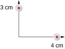
Two wires, both carrying current out of the page, have a current of magnitude 5.0 mA. The first wire is located at (0.0 cm, 3.0 cm) while the other wire is located at (4.0 cm, 0.0 cm) as shown in Figure 12.10. What is the magnetic force per unit length of the first wire on the second and the second wire on the first?
Strategy
Each wire produces a magnetic field felt by the other wire. The distance along the hypotenuse of the triangle between the wires is the radial distance used in the calculation to determine the force per unit length. Since both wires have currents flowing in the same direction, the direction of the force is toward each other.
Solution
Show Answer
The distance between the wires results from finding the hypotenuse of a triangle:
The force per unit length can then be calculated using the known currents in the wires:
The force from the first wire pulls the second wire. The angle between the radius and the x-axis is
The unit vector for this is calculated by
Therefore, the force per unit length from wire one on wire 2 is
The force per unit length from wire 2 on wire 1 is the negative of the previous answer:
Significance
These wires produced magnetic fields of equal magnitude but opposite directions at each other’s locations. Whether the fields are identical or not, the forces that the wires exert on each other are always equal in magnitude and opposite in direction (Newton’s third law).
Check Your Understanding
Two wires, both carrying current out of the page, have a current of magnitude 2.0 mA and 3.0 mA, respectively. The first wire is located at (0.0 cm, 5.0 cm) while the other wire is located at (12.0 cm, 0.0 cm). What is the magnitude of the magnetic force per unit length of the first wire on the second and the second wire on the first?
Show Solution
Both have a force per unit length of [latex]9.23\phantom{\rule{0.2em}{0ex}}×\phantom{\rule{0.2em}{0ex}}{10}^{\text{−12}}\phantom{\rule{0.2em}{0ex}}\text{N/m}[/latex]
Summary
- The force between two parallel currents [latex]{I}_{1}[/latex] and [latex]{I}_{2},[/latex] separated by a distance r, has a magnitude per unit length given by [latex]\frac{F}{l}=\frac{{\mu }_{0}{I}_{1}{I}_{2}}{2\pi r}.[/latex]
- The force is attractive if the currents are in the same direction, repulsive if they are in opposite directions.
Conceptual Questions
Compare and contrast the electric field of an infinite line of charge and the magnetic field of an infinite line of current.
Is [latex]\stackrel{\to }{\textbf{B}}[/latex] constant in magnitude for points that lie on a magnetic field line?
Show Solution
A magnetic field line gives the direction of the magnetic field at any point in space. The density of magnetic field lines indicates the strength of the magnetic field.
Problems
Two long, straight wires are parallel and 25 cm apart. (a) If each wire carries a current of 50 A in the same direction, what is the magnetic force per meter exerted on each wire? (b) Does the force pull the wires together or push them apart? (c) What happens if the currents flow in opposite directions?
Two long, straight wires are parallel and 10 cm apart. One carries a current of 2.0 A, the other a current of 5.0 A. (a) If the two currents flow in opposite directions, what is the magnitude and direction of the force per unit length of one wire on the other? (b) What is the magnitude and direction of the force per unit length if the currents flow in the same direction?
Show Solution
a. [latex]F\phantom{\rule{0.1em}{0ex}}\text{/}\phantom{\rule{0.1em}{0ex}}l=8\phantom{\rule{0.2em}{0ex}}×\phantom{\rule{0.2em}{0ex}}{10}^{\text{−6}}\text{N/m}[/latex] away from the other wire; b. [latex]F\phantom{\rule{0.1em}{0ex}}\text{/}\phantom{\rule{0.1em}{0ex}}l=8\phantom{\rule{0.2em}{0ex}}×\phantom{\rule{0.2em}{0ex}}{10}^{\text{−6}}\text{N/m}[/latex] toward the other wire
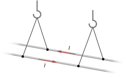
Two long, parallel wires are hung by cords of length 5.0 cm, as shown in the accompanying figure. Each wire has a mass per unit length of 30 g/m, and they carry the same current in opposite directions. What is the current if the cords hang at [latex]6.0\text{°}[/latex] with respect to the vertical?
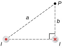
A circuit with current I has two long parallel wire sections that carry current in opposite directions. Find magnetic field at a point P near these wires that is a distance a from one wire and b from the other wire as shown in the figure.
Show Solution
[latex]B=\frac{{\mu }_{o}I}{2\pi {a}^{2}b}\left(\left({a}_{2}+{b}_{2}\right)\hat{\textbf{i}}+b\sqrt{\left({a}^{2}–{b}^{2}\right)}\hat{\textbf{j}}\right)[/latex]
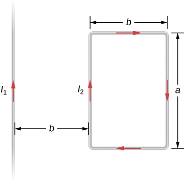
The infinite, straight wire shown in the accompanying figure carries a current [latex]{I}_{1}.[/latex] The rectangular loop, whose long sides are parallel to the wire, carries a current [latex]{I}_{2}.[/latex] What are the magnitude and direction of the force on the rectangular loop due to the magnetic field of the wire?
Licenses and Attributions
Magnetic Force between Two Parallel Currents. Authored by: OpenStax College. Located at: https://openstax.org/books/university-physics-volume-2/pages/12-3-magnetic-force-between-two-parallel-currents. License: CC BY: Attribution. License Terms: Download for free at https://openstax.org/books/university-physics-volume-2/pages/1-introduction
