
Chapter 15. Alternating-Current Circuits
15.3 RLC Series Circuits with AC
Learning Objectives
By the end of the section, you will be able to:
- Describe how the current varies in a resistor, a capacitor, and an inductor while in series with an ac power source
- Use phasors to understand the phase angle of a resistor, capacitor, and inductor ac circuit and to understand what that phase angle means
- Calculate the impedance of a circuit
The ac circuit shown in Figure 15.11, called an RLC series circuit, is a series combination of a resistor, capacitor, and inductor connected across an ac source. It produces an emf of
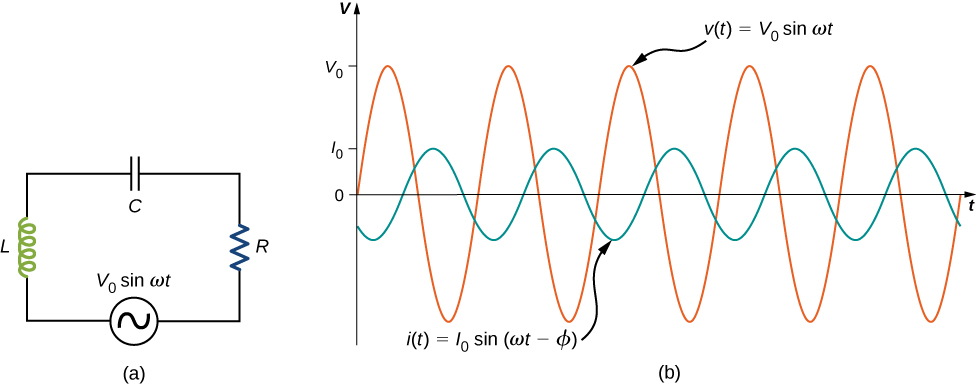
Since the elements are in series, the same current flows through each element at all points in time. The relative phase between the current and the emf is not obvious when all three elements are present. Consequently, we represent the current by the general expression
where [latex]{I}_{0}[/latex] is the current amplitude and [latex]\varphi[/latex] is the phase angle between the current and the applied voltage. The phase angle is thus the amount by which the voltage and current are out of phase with each other in a circuit. Our task is to find [latex]{I}_{0}\phantom{\rule{0.2em}{0ex}}\text{and}\phantom{\rule{0.2em}{0ex}}\varphi .[/latex]
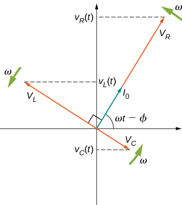
A phasor diagram involving [latex]i\left(t\right),{v}_{R}\left(t\right),{v}_{C}\left(t\right),\phantom{\rule{0.2em}{0ex}}\text{and}\phantom{\rule{0.2em}{0ex}}{v}_{L}\left(t\right)[/latex] is helpful for analyzing the circuit. As shown in Figure 15.12, the phasor representing [latex]{v}_{R}\left(t\right)[/latex] points in the same direction as the phasor for [latex]i\left(t\right);[/latex] its amplitude is [latex]{V}_{R}={I}_{0}R.[/latex] The [latex]{v}_{C}\left(t\right)[/latex] phasor lags the i(t) phasor by [latex]\pi \text{/}2[/latex] rad and has the amplitude [latex]{V}_{C}={I}_{0}{X}_{C}.[/latex] The phasor for [latex]{v}_{L}\left(t\right)[/latex] leads the i(t) phasor by [latex]\pi \text{/}2[/latex] rad and has the amplitude [latex]{V}_{L}={I}_{0}{X}_{L}.[/latex]
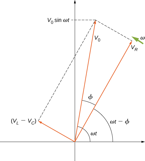
At any instant, the voltage across the RLC combination is [latex]{v}_{R}\left(t\right)+{v}_{L}\left(t\right)+{v}_{C}\left(t\right)=v\left(t\right),[/latex] the emf of the source. Since a component of a sum of vectors is the sum of the components of the individual vectors—for example, [latex]{\left(A+B\right)}_{y}={A}_{y}+{B}_{y}[/latex] —the projection of the vector sum of phasors onto the vertical axis is the sum of the vertical projections of the individual phasors. Hence, if we add vectorially the phasors representing [latex]{v}_{R}\left(t\right),{v}_{L}\left(t\right),\phantom{\rule{0.2em}{0ex}}\text{and}\phantom{\rule{0.2em}{0ex}}{v}_{C}\left(t\right)[/latex] and then find the projection of the resultant onto the vertical axis, we obtain
The vector sum of the phasors is shown in Figure 15.13. The resultant phasor has an amplitude [latex]{V}_{0}[/latex] and is directed at an angle [latex]\varphi[/latex] with respect to the [latex]{v}_{R}\left(t\right),[/latex] or i(t), phasor. The projection of this resultant phasor onto the vertical axis is [latex]v\left(t\right)={V}_{0}\phantom{\rule{0.2em}{0ex}}\text{sin}\phantom{\rule{0.2em}{0ex}}\omega t.[/latex] We can easily determine the unknown quantities [latex]{I}_{0}[/latex] and [latex]\varphi[/latex] from the geometry of the phasor diagram. For the phase angle,
and after cancellation of [latex]{I}_{0},[/latex] this becomes
Furthermore, from the Pythagorean theorem,
The current amplitude is therefore the ac version of Ohm’s law:
where
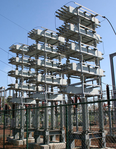
is known as the impedance of the circuit. Its unit is the ohm, and it is the ac analog to resistance in a dc circuit, which measures the combined effect of resistance, capacitive reactance, and inductive reactance (Figure 15.14).
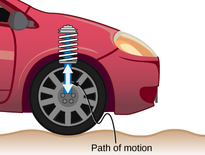
The RLC circuit is analogous to the wheel of a car driven over a corrugated road (Figure 15.15). The regularly spaced bumps in the road drive the wheel up and down; in the same way, a voltage source increases and decreases. The shock absorber acts like the resistance of the RLC circuit, damping and limiting the amplitude of the oscillation. Energy within the wheel system goes back and forth between kinetic and potential energy stored in the car spring, analogous to the shift between a maximum current, with energy stored in an inductor, and no current, with energy stored in the electric field of a capacitor. The amplitude of the wheel’s motion is at a maximum if the bumps in the road are hit at the resonant frequency, which we describe in more detail in Resonance in an AC Circuit.
Problem-Solving Strategy: AC Circuits
To analyze an ac circuit containing resistors, capacitors, and inductors, it is helpful to think of each device’s reactance and find the equivalent reactance using the rules we used for equivalent resistance in the past. Phasors are a great method to determine whether the emf of the circuit has positive or negative phase (namely, leads or lags other values). A mnemonic device of “ELI the ICE man” is sometimes used to remember that the emf (E) leads the current (I) in an inductor (L) and the current (I) leads the emf (E) in a capacitor (C).
Use the following steps to determine the emf of the circuit by phasors:
- Draw the phasors for voltage across each device: resistor, capacitor, and inductor, including the phase angle in the circuit.
- If there is both a capacitor and an inductor, find the net voltage from these two phasors, since they are antiparallel.
- Find the equivalent phasor from the phasor in step 2 and the resistor’s phasor using trigonometry or components of the phasors. The equivalent phasor found is the emf of the circuit.
Example
An RLC Series Circuit
The output of an ac generator connected to an RLC series combination has a frequency of 200 Hz and an amplitude of 0.100 V. If [latex]R=4.00\phantom{\rule{0.2em}{0ex}}\text{Ω},[/latex] [latex]L=3.00\phantom{\rule{0.2em}{0ex}}×\phantom{\rule{0.2em}{0ex}}{10}^{-3}\phantom{\rule{0.2em}{0ex}}\text{H,}[/latex] and [latex]C=8.00\phantom{\rule{0.2em}{0ex}}×\phantom{\rule{0.2em}{0ex}}{10}^{-4}\phantom{\rule{0.2em}{0ex}}\text{F,}[/latex] what are (a) the capacitive reactance, (b) the inductive reactance, (c) the impedance, (d) the current amplitude, and (e) the phase difference between the current and the emf of the generator?
Strategy
The reactances and impedance in (a)–(c) are found by substitutions into Equation 15.3, Equation 15.8, and Equation 15.11, respectively. The current amplitude is calculated from the peak voltage and the impedance. The phase difference between the current and the emf is calculated by the inverse tangent of the difference between the reactances divided by the resistance.
Solution
Show Answer
- From Equation 15.3, the capacitive reactance is
[latex]{X}_{C}=\frac{1}{\omega C}=\frac{1}{2\pi \left(200\phantom{\rule{0.2em}{0ex}}\text{Hz}\right)\left(8.00\phantom{\rule{0.2em}{0ex}}×\phantom{\rule{0.2em}{0ex}}{10}^{-4}\phantom{\rule{0.2em}{0ex}}\text{F}\right)}=0.995\phantom{\rule{0.2em}{0ex}}\text{Ω}\text{.}[/latex] - From Equation 15.8, the inductive reactance is
[latex]{X}_{L}=\omega L=2\pi \left(200\phantom{\rule{0.2em}{0ex}}\text{Hz}\right)\left(3.00\phantom{\rule{0.2em}{0ex}}×\phantom{\rule{0.2em}{0ex}}{10}^{-3}\phantom{\rule{0.2em}{0ex}}\text{H}\right)=3.77\phantom{\rule{0.2em}{0ex}}\text{Ω}\text{.}[/latex] - Substituting the values of R, [latex]{X}_{C}[/latex], and [latex]{X}_{L}[/latex] into Equation 15.11, we obtain for the impedance
[latex]Z=\sqrt{{\left(4.00\phantom{\rule{0.2em}{0ex}}\text{Ω}\right)}^{2}+{\left(3.77\phantom{\rule{0.2em}{0ex}}\text{Ω}-0.995\phantom{\rule{0.2em}{0ex}}\text{Ω}\right)}^{2}}=4.87\phantom{\rule{0.2em}{0ex}}\text{Ω}\text{.}[/latex] - The current amplitude is
[latex]{I}_{0}=\frac{{V}_{0}}{Z}=\frac{0.100\phantom{\rule{0.2em}{0ex}}\text{V}}{4.87\phantom{\rule{0.2em}{0ex}}\text{Ω}}=2.05\phantom{\rule{0.2em}{0ex}}×\phantom{\rule{0.2em}{0ex}}{10}^{-2}\text{A}\text{.}[/latex] - From Equation 15.9, the phase difference between the current and the emf is
[latex]\varphi ={\text{tan}}^{-1}\frac{{X}_{L}-{X}_{C}}{R}={\text{tan}}^{-1}\frac{2.77\phantom{\rule{0.2em}{0ex}}\text{Ω}}{4.00\phantom{\rule{0.2em}{0ex}}\text{Ω}}=0.607\phantom{\rule{0.2em}{0ex}}\text{rad}\text{.}[/latex]
Significance
The phase angle is positive because the reactance of the inductor is larger than the reactance of the capacitor.
Check Your Understanding
Find the voltages across the resistor, the capacitor, and the inductor in the circuit of Figure 15.11 using [latex]v\left(t\right)={V}_{0}\phantom{\rule{0.2em}{0ex}}\text{sin}\phantom{\rule{0.2em}{0ex}}\omega t[/latex] as the output of the ac generator.
Show Solution
[latex]\begin{array}{c}{v}_{R}=\left({V}_{0}R\text{/}Z\right)\phantom{\rule{0.2em}{0ex}}\text{sin}\phantom{\rule{0.2em}{0ex}}\left(\omega t-\varphi \right);{v}_{C}=\left({V}_{0}{X}_{C}\text{/}Z\right)\phantom{\rule{0.2em}{0ex}}\text{sin}\phantom{\rule{0.2em}{0ex}}\left(\omega t-\varphi +\pi \text{/}2\right)=\text{−}\left({V}_{0}{X}_{C}\text{/}Z\right)\text{cos}\left(\omega t-\varphi \right);\hfill \\ {v}_{L}=\left({V}_{0}{X}_{L}\text{/}Z\right)\phantom{\rule{0.2em}{0ex}}\text{sin}\phantom{\rule{0.2em}{0ex}}\left(\omega t-\varphi +\pi \text{/}2\right)=\left({V}_{0}{X}_{L}\text{/}Z\right)\text{cos}\left(\omega t-\varphi \right)\hfill \end{array}[/latex]
Summary
- An RLC series circuit is a resistor, capacitor, and inductor series combination across an ac source.
- The same current flows through each element of an RLC series circuit at all points in time.
- The counterpart of resistance in a dc circuit is impedance, which measures the combined effect of resistors, capacitors, and inductors. The maximum current is defined by the ac version of Ohm’s law.
- Impedance has units of ohms and is found using the resistance, the capacitive reactance, and the inductive reactance.
Conceptual Questions
In an RLC series circuit, can the voltage measured across the capacitor be greater than the voltage of the source? Answer the same question for the voltage across the inductor.
Show Solution
yes for both
Problems
What is the impedance of a series combination of a [latex]50\text{-Ω}[/latex] resistor, a [latex]5.0\text{-}\mu \text{F}[/latex] capacitor, and a [latex]10\text{-}\mu \text{F}[/latex] capacitor at a frequency of 2.0 kHz?
A resistor and capacitor are connected in series across an ac generator. The emf of the generator is given by [latex]v\left(t\right)={V}_{0}\phantom{\rule{0.2em}{0ex}}\text{cos}\phantom{\rule{0.2em}{0ex}}\omega t,[/latex] where [latex]{V}_{0}=120\phantom{\rule{0.2em}{0ex}}\text{V,}[/latex] [latex]\omega =120\pi \phantom{\rule{0.2em}{0ex}}\text{rad/s},[/latex] [latex]R=400\phantom{\rule{0.2em}{0ex}}\text{Ω}[/latex], and [latex]C=4.0\mu \text{F}[/latex]. (a) What is the impedance of the circuit? (b) What is the amplitude of the current through the resistor? (c) Write an expression for the current through the resistor. (d) Write expressions representing the voltages across the resistor and across the capacitor.
Show Solution
a. [latex]770\phantom{\rule{0.2em}{0ex}}\text{Ω}[/latex]; b. 0.16 A; c. [latex]I=\left(0.16\phantom{\rule{0.2em}{0ex}}\text{A}\right)\text{cos}\left(120\pi t\right)[/latex]; d. [latex]{v}_{R}=62\phantom{\rule{0.2em}{0ex}}\text{cos}\left(120\pi t\right)[/latex]; [latex]{v}_{C}=103\phantom{\rule{0.2em}{0ex}}\text{cos}\left(120\pi t-\pi \text{/}2\right)[/latex]
A resistor and inductor are connected in series across an ac generator. The emf of the generator is given by [latex]v\left(t\right)={V}_{0}\phantom{\rule{0.2em}{0ex}}\text{cos}\phantom{\rule{0.2em}{0ex}}\omega t,[/latex] where [latex]{V}_{0}=120\phantom{\rule{0.2em}{0ex}}\text{V}[/latex] and [latex]\omega =120\pi \phantom{\rule{0.2em}{0ex}}\text{rad/s;}[/latex] also, [latex]R=400\phantom{\rule{0.2em}{0ex}}\text{Ω}[/latex] and [latex]L=1.5\phantom{\rule{0.2em}{0ex}}\text{H}\text{.}[/latex] (a) What is the impedance of the circuit? (b) What is the amplitude of the current through the resistor? (c) Write an expression for the current through the resistor. (d) Write expressions representing the voltages across the resistor and across the inductor.
In an RLC series circuit, the voltage amplitude and frequency of the source are 100 V and 500 Hz, respectively, an [latex]R=500\phantom{\rule{0.2em}{0ex}}\text{Ω}\text{,}[/latex] [latex]L=0.20\phantom{\rule{0.2em}{0ex}}\text{H,}[/latex] and [latex]C=2.0\mu \text{F}\text{.}[/latex] (a) What is the impedance of the circuit? (b) What is the amplitude of the current from the source? (c) If the emf of the source is given by [latex]v\left(t\right)=\left(100\phantom{\rule{0.2em}{0ex}}\text{V}\right)\phantom{\rule{0.2em}{0ex}}\text{sin}\phantom{\rule{0.2em}{0ex}}1000\pi t[/latex], how does the current vary with time? (d) Repeat the calculations with C changed to [latex]0.20\mu \text{F}\text{.}[/latex]
Show Solution
a. [latex]690\phantom{\rule{0.2em}{0ex}}\text{Ω}[/latex]; b. 0.15 A; c. [latex]I=\left(0.15\text{A}\right)\phantom{\rule{0.2em}{0ex}}\text{sin}\phantom{\rule{0.2em}{0ex}}\left(1000\pi t-0.753\right)[/latex]; d. [latex]1100\phantom{\rule{0.2em}{0ex}}\text{Ω}[/latex], 0.092 A, [latex]I=\left(0.092\text{A}\right)\phantom{\rule{0.2em}{0ex}}\text{sin}\phantom{\rule{0.2em}{0ex}}\left(1000\pi t+1.09\right)[/latex]
An RLC series circuit with [latex]R=600\phantom{\rule{0.2em}{0ex}}\text{Ω}[/latex], [latex]L=30\phantom{\rule{0.2em}{0ex}}\text{mH,}[/latex] and [latex]C=0.050\mu \text{F}[/latex] is driven by an ac source whose frequency and voltage amplitude are 500 Hz and 50 V, respectively. (a) What is the impedance of the circuit? (b) What is the amplitude of the current in the circuit? (c) What is the phase angle between the emf of the source and the current?
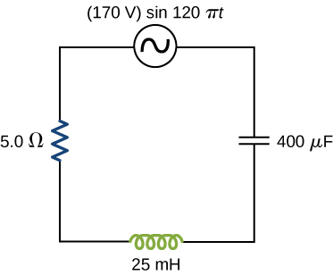
For the circuit shown below, what are (a) the total impedance and (b) the phase angle between the current and the emf? (c) Write an expression for [latex]i\left(t\right).[/latex]
Show Solution
a. [latex]5.7\phantom{\rule{0.2em}{0ex}}\text{Ω}[/latex]; b. [latex]29\text{°}[/latex]; c. [latex]I\text{}=\left(30.\phantom{\rule{0.2em}{0ex}}\text{A}\right)\text{cos}\left(120\pi t+0.51\right)[/latex]
Glossary
- impedance
- ac analog to resistance in a dc circuit, which measures the combined effect of resistance, capacitive reactance, and inductive reactance
- phase angle
- amount by which the voltage and current are out of phase with each other in a circuit
Licenses and Attributions
RLC Series Circuits with AC. Authored by: OpenStax College. Located at: https://openstax.org/books/university-physics-volume-2/pages/15-3-rlc-series-circuits-with-ac. License: CC BY: Attribution. License Terms: Download for free at https://openstax.org/books/university-physics-volume-2/pages/1-introduction
