
9 Linear Momentum and Collisions
9.6 Center of Mass
Learning Objectives
By the end of this section, you will be able to:
- Explain the meaning and usefulness of the concept of center of mass
- Calculate the center of mass of a given system
- Apply the center of mass concept in two and three dimensions
- Calculate the velocity and acceleration of the center of mass
We have been avoiding an important issue up to now: When we say that an object moves (more correctly, accelerates) in a way that obeys Newton’s second law, we have been ignoring the fact that all objects are actually made of many constituent particles. A car has an engine, steering wheel, seats, passengers; a football is leather and rubber surrounding air; a brick is made of atoms. There are many different types of particles, and they are generally not distributed uniformly in the object. How do we include these facts into our calculations?
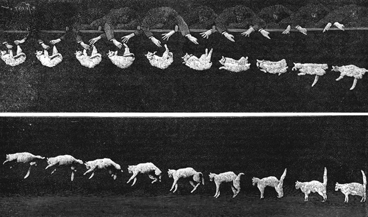
Then too, an extended object might change shape as it moves, such as a water balloon or a cat falling (Figure). This implies that the constituent particles are applying internal forces on each other, in addition to the external force that is acting on the object as a whole. We want to be able to handle this, as well.
The problem before us, then, is to determine what part of an extended object is obeying Newton’s second law when an external force is applied and to determine how the motion of the object as a whole is affected by both the internal and external forces.
Be warned: To treat this new situation correctly, we must be rigorous and completely general. We won’t make any assumptions about the nature of the object, or of its constituent particles, or either the internal or external forces. Thus, the arguments will be complex.
Internal and External Forces
Suppose we have an extended object of mass M, made of N interacting particles. Let’s label their masses as [latex]{m}_{j}[/latex], where [latex]j=1,2,3,\dots,N[/latex]. Note that
If we apply some net external force [latex]{\mathbf{\overset{\to }{F}}}_{\text{ext}}[/latex] on the object, every particle experiences some “share” or some fraction of that external force. Let:
Notice that these fractions of the total force are not necessarily equal; indeed, they virtually never are. (They can be, but they usually aren’t.) In general, therefore,
Next, we assume that each of the particles making up our object can interact (apply forces on) every other particle of the object. We won’t try to guess what kind of forces they are; but since these forces are the result of particles of the object acting on other particles of the same object, we refer to them as internal forces [latex]{\mathbf{\overset{\to }{f}}}_{j}^{\text{int}}[/latex]; thus:
[latex]{\mathbf{\overset{\to }{f}}}_{j}^{\text{int}}=[/latex] the net internal force that the jth particle experiences from all the other particles that make up the object.
Now, the net force, internal plus external, on the jth particle is the vector sum of these:
where again, this is for all N particles; [latex]j=1,2,3,\dots ,N[/latex].
As a result of this fractional force, the momentum of each particle gets changed:
The net force [latex]\mathbf{\overset{\to }{F}}[/latex] on the object is the vector sum of these forces:
This net force changes the momentum of the object as a whole, and the net change of momentum of the object must be the vector sum of all the individual changes of momentum of all of the particles:
Combining Figure and Figure gives
Let’s now think about these summations. First consider the internal forces term; remember that each [latex]{\mathbf{\overset{\to }{f}}}_{j}^{\text{int}}[/latex] is the force on the jth particle from the other particles in the object. But by Newton’s third law, for every one of these forces, there must be another force that has the same magnitude, but the opposite sign (points in the opposite direction). These forces do not cancel; however, that’s not what we’re doing in the summation. Rather, we’re simply mathematically adding up all the internal force vectors. That is, in general, the internal forces for any individual part of the object won’t cancel, but when all the internal forces are added up, the internal forces must cancel in pairs. It follows, therefore, that the sum of all the internal forces must be zero:
(This argument is subtle, but crucial; take plenty of time to completely understand it.)
For the external forces, this summation is simply the total external force that was applied to the whole object:
As a result,
This is an important result. Figure tells us that the total change of momentum of the entire object (all N particles) is due only to the external forces; the internal forces do not change the momentum of the object as a whole. This is why you can’t lift yourself in the air by standing in a basket and pulling up on the handles: For the system of you + basket, your upward pulling force is an internal force.
Force and Momentum
Remember that our actual goal is to determine the equation of motion for the entire object (the entire system of particles). To that end, let’s define:
[latex]{\mathbf{\overset{\to }{p}}}_{\text{CM}}=[/latex] the total momentum of the system of N particles (the reason for the subscript will become clear shortly)
Then we have
and therefore Figure can be written simply as
Since this change of momentum is caused by only the net external force, we have dropped the “ext” subscript.
This is Newton’s second law, but now for the entire extended object. If this feels a bit anticlimactic, remember what is hiding inside it: [latex]{\mathbf{\overset{\to }{p}}}_{\text{CM}}[/latex] is the vector sum of the momentum of (in principle) hundreds of thousands of billions of billions of particles [latex](6.02\times {10}^{23})[/latex], all caused by one simple net external force—a force that you can calculate.
Center of Mass
Our next task is to determine what part of the extended object, if any, is obeying Figure.
It’s tempting to take the next step; does the following equation mean anything?
If it does mean something (acceleration of what, exactly?), then we could write
and thus
which follows because the derivative of a sum is equal to the sum of the derivatives.
Now, [latex]{\mathbf{\overset{\to }{p}}}_{j}[/latex] is the momentum of the jth particle. Defining the positions of the constituent particles (relative to some coordinate system) as [latex]{\mathbf{\overset{\to }{r}}}_{j}=({x}_{j},{y}_{j},{z}_{j})[/latex], we thus have
Substituting back, we obtain
Dividing both sides by M (the total mass of the extended object) gives us
Thus, the point in the object that traces out the trajectory dictated by the applied force in Figure is inside the parentheses in Figure.
Looking at this calculation, notice that (inside the parentheses) we are calculating the product of each particle’s mass with its position, adding all N of these up, and dividing this sum by the total mass of particles we summed. This is reminiscent of an average; inspired by this, we’ll (loosely) interpret it to be the weighted average position of the mass of the extended object. It’s actually called the center of mass of the object. Notice that the position of the center of mass has units of meters; that suggests a definition:
So, the point that obeys Figure (and therefore Figure as well) is the center of mass of the object, which is located at the position vector [latex]{\mathbf{\overset{\to }{r}}}_{\text{CM}}[/latex].
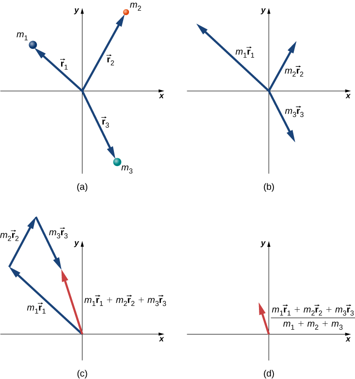
It may surprise you to learn that there does not have to be any actual mass at the center of mass of an object. For example, a hollow steel sphere with a vacuum inside it is spherically symmetrical (meaning its mass is uniformly distributed about the center of the sphere); all of the sphere’s mass is out on its surface, with no mass inside. But it can be shown that the center of mass of the sphere is at its geometric center, which seems reasonable. Thus, there is no mass at the position of the center of mass of the sphere. (Another example is a doughnut.) The procedure to find the center of mass is illustrated in Figure.
Since [latex]{\mathbf{\overset{\to }{r}}}_{j}={x}_{j}\mathbf{\hat{i}}+{y}_{j}\mathbf{\hat{j}}+{z}_{j}\mathbf{\hat{k}}[/latex], it follows that:
and thus
Therefore, you can calculate the components of the center of mass vector individually.
Finally, to complete the kinematics, the instantaneous velocity of the center of mass is calculated exactly as you might suspect:
and this, like the position, has x-, y-, and z-components.
To calculate the center of mass in actual situations, we recommend the following procedure:
Problem-Solving Strategy: Calculating the Center of Mass
The center of mass of an object is a position vector. Thus, to calculate it, do these steps:
- Define your coordinate system. Typically, the origin is placed at the location of one of the particles. This is not required, however.
- Determine the x, y, z-coordinates of each particle that makes up the object.
- Determine the mass of each particle, and sum them to obtain the total mass of the object. Note that the mass of the object at the origin must be included in the total mass.
- Calculate the x-, y-, and z-components of the center of mass vector, using Figure, Figure, and Figure.
- If required, use the Pythagorean theorem to determine its magnitude.
Here are two examples that will give you a feel for what the center of mass is.
Example
Center of Mass of the Earth-Moon System
Using data from text appendix, determine how far the center of mass of the Earth-moon system is from the center of Earth. Compare this distance to the radius of Earth, and comment on the result. Ignore the other objects in the solar system.
Strategy
We get the masses and separation distance of the Earth and moon, impose a coordinate system, and use Figure with just [latex]N=2[/latex] objects. We use a subscript “e” to refer to Earth, and subscript “m” to refer to the moon.
Solution
Define the origin of the coordinate system as the center of Earth. Then, with just two objects, Figure becomes
From Appendix D,
We defined the center of Earth as the origin, so [latex]{r}_{\text{e}}=\text{0 m}[/latex]. Inserting these into the equation for R gives
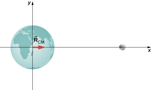
Significance
The radius of Earth is [latex]6.37\times {10}^{6}\,\text{m}[/latex], so the center of mass of the Earth-moon system is (6.37 − 4.64) [latex]×\,{10}^{6}\,\text{m}=1.73\times {10}^{6}\,\text{m}=1730\,\text{km}[/latex] (roughly 1080 miles) below the surface of Earth. The location of the center of mass is shown (not to scale).
Check Your Understanding
Suppose we included the sun in the system. Approximately where would the center of mass of the Earth-moon-sun system be located? (Feel free to actually calculate it.)
Show Solution
The average radius of Earth’s orbit around the Sun is [latex]1.496\times {10}^{9}\,\text{m}[/latex]. Taking the Sun to be the origin, and noting that the mass of the Sun is approximately the same as the masses of the Sun, Earth, and Moon combined, the center of mass of the Earth + Moon system and the Sun is
[latex]\begin{array}{cc}\hfill {R}_{\text{CM}}& =\frac{{m}_{\mathrm{Sun}}{R}_{\mathrm{Sun}}+{m}_{\text{em}}{R}_{\text{em}}}{{m}_{\mathrm{Sun}}}\hfill \\ & =\frac{(1.989\times {10}^{30}\,\text{kg})(0)+(5.97\times {10}^{24}\,\text{kg}+7.36\times {10}^{22}\,\text{kg})(1.496\times {10}^{9}\,\text{m})}{1.989\times {10}^{30}\,\text{kg}}\hfill \\ & =4.6\,\text{km}\hfill \end{array}[/latex]
Thus, the center of mass of the Sun, Earth, Moon system is 4.6 km from the center of the Sun.
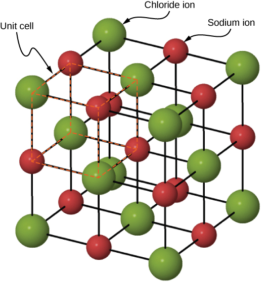
Example
Center of Mass of a Salt CrystalFigure shows a single crystal of sodium chloride—ordinary table salt. The sodium and chloride ions form a single unit, NaCl. When multiple NaCl units group together, they form a cubic lattice. The smallest possible cube (called the unit cell) consists of four sodium ions and four chloride ions, alternating. The length of one edge of this cube (i.e., the bond length) is [latex]2.36\times {10}^{-10}\,\text{m}[/latex]. Find the location of the center of mass of the unit cell. Specify it either by its coordinates [latex]({r}_{\text{CM,}x},{r}_{\text{CM,}y},{r}_{\text{CM,}z})[/latex], or by [latex]{r}_{\text{CM}}[/latex] and two angles.
Strategy
We can look up all the ion masses. If we impose a coordinate system on the unit cell, this will give us the positions of the ions. We can then apply Figure, Figure, and Figure (along with the Pythagorean theorem).
Solution
Define the origin to be at the location of the chloride ion at the bottom left of the unit cell. Figure shows the coordinate system.
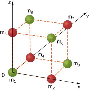
There are eight ions in this crystal, so N = 8:
The mass of each of the chloride ions is
so we have
For the sodium ions,
The total mass of the unit cell is therefore
From the geometry, the locations are
Substituting:
Similar calculations give [latex]{r}_{\text{CM,}y}={r}_{\text{CM,}z}=1.18\times {10}^{-10}\,\text{m}[/latex] (you could argue that this must be true, by symmetry, but it’s a good idea to check).
SignificanceAlthough this is a great exercise to determine the center of mass given a Chloride ion at the origin, in fact the origin could be chosen at any location. Therefore, there is no meaningful application of the center of mass of a unit cell beyond as an exercise.
Check Your Understanding
Suppose you have a macroscopic salt crystal (that is, a crystal that is large enough to be visible with your unaided eye). It is made up of a huge number of unit cells. Is the center of mass of this crystal necessarily at the geometric center of the crystal?
Show Solution
On a macroscopic scale, the size of a unit cell is negligible and the crystal mass may be considered to be distributed homogeneously throughout the crystal. Thus,
[latex]{\mathbf{\overset{\to }{r}}}_{\text{CM}}=\frac{1}{M}\sum _{j=1}^{N}{m}_{j}{\mathbf{\overset{\to }{r}}}_{j}=\frac{1}{M}\sum _{j=1}^{N}m{\mathbf{\overset{\to }{r}}}_{j}=\frac{m}{M}\sum _{j=1}^{N}{\mathbf{\overset{\to }{r}}}_{j}=\frac{Nm}{M}\,\frac{\sum _{j=1}^{N}{\mathbf{\overset{\to }{r}}}_{j}}{N}[/latex]
where we sum over the number N of unit cells in the crystal and m is the mass of a unit cell. Because Nm = M, we can write
[latex]{\mathbf{\overset{\to }{r}}}_{\text{CM}}=\frac{m}{M}\sum _{j=1}^{N}{\mathbf{\overset{\to }{r}}}_{j}=\frac{Nm}{M}\,\frac{\sum _{j=1}^{N}{\mathbf{\overset{\to }{r}}}_{j}}{N}=\frac{1}{N}\sum _{j=1}^{N}{\mathbf{\overset{\to }{r}}}_{j}.[/latex]
This is the definition of the geometric center of the crystal, so the center of mass is at the same point as the geometric center.
Two crucial concepts come out of these examples:
- As with all problems, you must define your coordinate system and origin. For center-of-mass calculations, it often makes sense to choose your origin to be located at one of the masses of your system. That choice automatically defines its distance in Figure to be zero. However, you must still include the mass of the object at your origin in your calculation of M, the total mass Figure. In the Earth-moon system example, this means including the mass of Earth. If you hadn’t, you’d have ended up with the center of mass of the system being at the center of the moon, which is clearly wrong.
- In the second example (the salt crystal), notice that there is no mass at all at the location of the center of mass. This is an example of what we stated above, that there does not have to be any actual mass at the center of mass of an object.
Center of Mass of Continuous Objects
If the object in question has its mass distributed uniformly in space, rather than as a collection of discrete particles, then [latex]{m}_{j}\to dm[/latex], and the summation becomes an integral:
In this context, r is a characteristic dimension of the object (the radius of a sphere, the length of a long rod). To generate an integrand that can actually be calculated, you need to express the differential mass element dm as a function of the mass density of the continuous object, and the dimension r. An example will clarify this.
Example
CM of a Uniform Thin Hoop
Find the center of mass of a uniform thin hoop (or ring) of mass M and radius r.
Strategy
First, the hoop’s symmetry suggests the center of mass should be at its geometric center. If we define our coordinate system such that the origin is located at the center of the hoop, the integral should evaluate to zero.
We replace dm with an expression involving the density of the hoop and the radius of the hoop. We then have an expression we can actually integrate. Since the hoop is described as “thin,” we treat it as a one-dimensional object, neglecting the thickness of the hoop. Therefore, its density is expressed as the number of kilograms of material per meter. Such a density is called a linear mass density, and is given the symbol [latex]\lambda[/latex]; this is the Greek letter “lambda,” which is the equivalent of the English letter “l” (for “linear”).
Since the hoop is described as uniform, this means that the linear mass density [latex]\lambda[/latex] is constant. Thus, to get our expression for the differential mass element dm, we multiply [latex]\lambda[/latex] by a differential length of the hoop, substitute, and integrate (with appropriate limits for the definite integral).
Solution
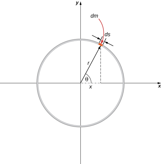
First, define our coordinate system and the relevant variables (Figure).
The center of mass is calculated with Figure:
We have to determine the limits of integration a and b. Expressing [latex]\mathbf{\overset{\to }{r}}[/latex] in component form gives us
In the diagram, we highlighted a piece of the hoop that is of differential length ds; it therefore has a differential mass [latex]dm=\lambda ds[/latex]. Substituting:
However, the arc length ds subtends a differential angle [latex]d\theta[/latex], so we have
and thus
One more step: Since [latex]\lambda[/latex] is the linear mass density, it is computed by dividing the total mass by the length of the hoop:
giving us
Notice that the variable of integration is now the angle [latex]\theta[/latex]. This tells us that the limits of integration (around the circular hoop) are [latex]\theta =\text{0 to}\,\theta =2\pi[/latex], so [latex]a=0[/latex] and [latex]b=2\pi[/latex]. Also, for convenience, we separate the integral into the x– and y-components of [latex]{\mathbf{\overset{\to }{r}}}_{\text{CM}}[/latex]. The final integral expression is
as expected.
Center of Mass and Conservation of Momentum
How does all this connect to conservation of momentum?
Suppose you have N objects with masses [latex]{m}_{1},{m}_{2},{m}_{3},...{m}_{N}[/latex] and initial velocities [latex]{\mathbf{\overset{\to }{v}}}_{1},{\mathbf{\overset{\to }{v}}}_{2},{\mathbf{\overset{\to }{v}}}_{3},...\text{,}{\mathbf{\overset{\to }{v}}}_{N}[/latex]. The center of mass of the objects is
Its velocity is
and thus the initial momentum of the center of mass is
After these masses move and interact with each other, the momentum of the center of mass is
But conservation of momentum tells us that the right-hand side of both equations must be equal, which says
This result implies that conservation of momentum is expressed in terms of the center of mass of the system. Notice that as an object moves through space with no net external force acting on it, an individual particle of the object may accelerate in various directions, with various magnitudes, depending on the net internal force acting on that object at any time. (Remember, it is only the vector sum of all the internal forces that vanishes, not the internal force on a single particle.) Thus, such a particle’s momentum will not be constant—but the momentum of the entire extended object will be, in accord with Figure.
Figure implies another important result: Since M represents the mass of the entire system of particles, it is necessarily constant. (If it isn’t, we don’t have a closed system, so we can’t expect the system’s momentum to be conserved.) As a result, Figure implies that, for a closed system,
That is to say, in the absence of an external force, the velocity of the center of mass never changes.
You might be tempted to shrug and say, “Well yes, that’s just Newton’s first law,” but remember that Newton’s first law discusses the constant velocity of a particle, whereas Figure applies to the center of mass of a (possibly vast) collection of interacting particles, and that there may not be any particle at the center of mass at all! So, this really is a remarkable result.
Example
Fireworks Display
When a fireworks rocket explodes, thousands of glowing fragments fly outward in all directions, and fall to Earth in an elegant and beautiful display (Figure). Describe what happens, in terms of conservation of momentum and center of mass.
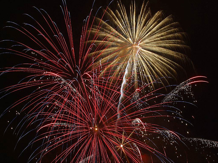
The picture shows radial symmetry about the central points of the explosions; this suggests the idea of center of mass. We can also see the parabolic motion of the glowing particles; this brings to mind projectile motion ideas.
Solution
Initially, the fireworks rocket is launched and flies more or less straight upward; this is the cause of the more-or-less-straight, white trail going high into the sky below the explosion in the upper-right of the picture (the yellow explosion). This trail is not parabolic because the explosive shell, during its launch phase, is actually a rocket; the impulse applied to it by the ejection of the burning fuel applies a force on the shell during the rise-time interval. (This is a phenomenon we will study in the next section.) The shell has multiple forces on it; thus, it is not in free-fall prior to the explosion.
At the instant of the explosion, the thousands of glowing fragments fly outward in a radially symmetrical pattern. The symmetry of the explosion is the result of all the internal forces summing to zero [latex](\sum _{j}{\mathbf{\overset{\to }{f}}}_{j}^{\text{int}}=0);[/latex] for every internal force, there is another that is equal in magnitude and opposite in direction.
However, as we learned above, these internal forces cannot change the momentum of the center of mass of the (now exploded) shell. Since the rocket force has now vanished, the center of mass of the shell is now a projectile (the only force on it is gravity), so its trajectory does become parabolic. The two red explosions on the left show the path of their centers of mass at a slightly longer time after explosion compared to the yellow explosion on the upper right.
In fact, if you look carefully at all three explosions, you can see that the glowing trails are not truly radially symmetric; rather, they are somewhat denser on one side than the other. Specifically, the yellow explosion and the lower middle explosion are slightly denser on their right sides, and the upper-left explosion is denser on its left side. This is because of the momentum of their centers of mass; the differing trail densities are due to the momentum each piece of the shell had at the moment of its explosion. The fragment for the explosion on the upper left of the picture had a momentum that pointed upward and to the left; the middle fragment’s momentum pointed upward and slightly to the right; and the right-side explosion clearly upward and to the right (as evidenced by the white rocket exhaust trail visible below the yellow explosion).
Finally, each fragment is a projectile on its own, thus tracing out thousands of glowing parabolas.
Significance
In the discussion above, we said, “…the center of mass of the shell is now a projectile (the only force on it is gravity)….” This is not quite accurate, for there may not be any mass at all at the center of mass; in which case, there could not be a force acting on it. This is actually just verbal shorthand for describing the fact that the gravitational forces on all the particles act so that the center of mass changes position exactly as if all the mass of the shell were always located at the position of the center of mass.
Check Your Understanding
How would the firework display change in deep space, far away from any source of gravity?
Show Solution
The explosions would essentially be spherically symmetric, because gravity would not act to distort the trajectories of the expanding projectiles.
You may sometimes hear someone describe an explosion by saying something like, “the fragments of the exploded object always move in a way that makes sure that the center of mass continues to move on its original trajectory.” This makes it sound as if the process is somewhat magical: how can it be that, in every explosion, it always works out that the fragments move in just the right way so that the center of mass’ motion is unchanged? Phrased this way, it would be hard to believe no explosion ever does anything differently.
The explanation of this apparently astonishing coincidence is: We defined the center of mass precisely so this is exactly what we would get. Recall that first we defined the momentum of the system:
We then concluded that the net external force on the system (if any) changed this momentum:
and then—and here’s the point—we defined an acceleration that would obey Newton’s second law. That is, we demanded that we should be able to write
which requires that
where the quantity inside the parentheses is the center of mass of our system. So, it’s not astonishing that the center of mass obeys Newton’s second law; we defined it so that it would.
Summary
- An extended object (made up of many objects) has a defined position vector called the center of mass.
- The center of mass can be thought of, loosely, as the average location of the total mass of the object.
- The center of mass of an object traces out the trajectory dictated by Newton’s second law, due to the net external force.
- The internal forces within an extended object cannot alter the momentum of the extended object as a whole.
Conceptual Questions
Suppose a fireworks shell explodes, breaking into three large pieces for which air resistance is negligible. How does the explosion affect the motion of the center of mass? How would it be affected if the pieces experienced significantly more air resistance than the intact shell?
Problems
Three point masses are placed at the corners of a triangle as shown in the figure below.
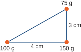
Find the center of mass of the three-mass system.
With the origin defined to be at the position of the 150-g mass, [latex]{x}_{\text{CM}}=-1.23\text{cm}[/latex] and [latex]{y}_{\text{CM}}=0.69\text{cm}[/latex]
Two particles of masses [latex]{m}_{1}[/latex] and [latex]{m}_{2}[/latex] separated by a horizontal distance D are released from the same height h at the same time. Find the vertical position of the center of mass of these two particles at a time before the two particles strike the ground. Assume no air resistance.
Two particles of masses [latex]{m}_{1}[/latex] and [latex]{m}_{2}[/latex] separated by a horizontal distance D are let go from the same height h at different times. Particle 1 starts at [latex]t=0[/latex], and particle 2 is let go at [latex]t=T[/latex]. Find the vertical position of the center of mass at a time before the first particle strikes the ground. Assume no air resistance.
Show Solution
[latex]{y}_{\text{CM}}=\left\{\begin{array}{c}\hfill \frac{h}{2}-\frac{1}{4}g{t}^{2},t\lt T\hfill \\ \hfill h-\frac{1}{2}g{t}^{2}-\frac{1}{4}g{T}^{2}+\frac{1}{2}gtT,t\ge T\hfill \end{array}\right.[/latex]
Two particles of masses [latex]{m}_{1}[/latex] and [latex]{m}_{2}[/latex] move uniformly in different circles of radii [latex]{R}_{1}[/latex] and [latex]{R}_{2}[/latex] about origin in the x, y-plane. The x– and y-coordinates of the center of mass and that of particle 1 are given as follows (where length is in meters and t in seconds):
[latex]{x}_{1}(t)=4\text{cos}(2t),{y}_{1}(t)=4\text{sin}(2t)[/latex]
and:
[latex]{x}_{\text{CM}}(t)=3\text{cos}(2t),{y}_{\text{CM}}(t)=3\text{sin}(2t).[/latex]
- Find the radius of the circle in which particle 1 moves.
- Find the x– and y-coordinates of particle 2 and the radius of the circle this particle moves.
Two particles of masses [latex]{m}_{1}[/latex] and [latex]{m}_{2}[/latex] move uniformly in different circles of radii [latex]{R}_{1}[/latex] and[latex]{R}_{2}[/latex] about the origin in the x, y-plane. The coordinates of the two particles in meters are given as follows ([latex]z=0[/latex] for both). Here t is in seconds:
[latex]\begin{array}{ccc}\hfill {x}_{1}(t)& =\hfill & 4\,\text{cos}(2t)\hfill \\ \hfill {y}_{1}(t)& =\hfill & 4\,\text{sin}(2t)\hfill \\ \hfill {x}_{2}(t)& =\hfill & 2\,\text{cos}(3t-\frac{\pi }{2})\hfill \\ \hfill {y}_{2}(t)& =\hfill & 2\,\text{sin}(3t-\frac{\pi }{2})\hfill \end{array}[/latex]
- Find the radii of the circles of motion of both particles.
- Find the x– and y-coordinates of the center of mass.
- Decide if the center of mass moves in a circle by plotting its trajectory.
a. [latex]{R}_{1}=4\,\text{m}[/latex], [latex]{R}_{2}=2\,\text{m}[/latex]; b. [latex]{X}_{\text{CM}}=\frac{{m}_{1}{x}_{1}+{m}_{2}{x}_{2}}{{m}_{1}+{m}_{2}},{Y}_{\text{CM}}=\frac{{m}_{1}{y}_{1}+{m}_{2}{y}_{2}}{{m}_{1}+{m}_{2}}[/latex]; c. yes, with [latex]R=\frac{1}{{m}_{1}+{m}_{2}}\sqrt{16{m}_{1}^{2}+4{m}_{2}^{2}}[/latex]Show Answer
Find the center of mass of a one-meter long rod, made of 50 cm of iron (density [latex]8\,\frac{\text{g}}{{\text{cm}}^{3}}[/latex]) and 50 cm of aluminum (density [latex]2.7\,\frac{\text{g}}{{\text{cm}}^{3}}[/latex]).
Find the center of mass of a rod of length L whose mass density changes from one end to the other quadratically. That is, if the rod is laid out along the x-axis with one end at the origin and the other end at [latex]x=L[/latex], the density is given by [latex]\rho (x)={\rho }_{0}+({\rho }_{1}-{\rho }_{0}){(\frac{x}{L})}^{2}[/latex], where [latex]{\rho }_{0}[/latex] and [latex]{\rho }_{1}[/latex] are constant values.
Show Solution
[latex]{x}_{cm}=\frac{3}{4}\,L(\frac{{\rho }_{1}+{\rho }_{0}}{{\rho }_{1}+2{\rho }_{0}})[/latex]
Find the center of mass of a rectangular block of length a and width b that has a nonuniform density such that when the rectangle is placed in the x,y-plane with one corner at the origin and the block placed in the first quadrant with the two edges along the x– and y-axes, the density is given by[latex]\rho (x,y)={\rho }_{0}x[/latex], where [latex]{\rho }_{0}[/latex] is a constant.
Find the center of mass of a rectangular material of length a and width b made up of a material of nonuniform density. The density is such that when the rectangle is placed in the xy-plane, the density is given by [latex]\rho (x,y)={\rho }_{0}xy[/latex].
Show Solution
[latex](\frac{2a}{3},\frac{2b}{3})[/latex]
A cube of side a is cut out of another cube of side b as shown in the figure below.
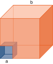
Find the location of the center of mass of the structure. (Hint: Think of the missing part as a negative mass overlapping a positive mass.)
Find the center of mass of a cone of uniform density that has a radius R at the base, height h, and mass M. Let the origin be at the center of the base of the cone and have +z going through the cone vertex.
Show Solution
[latex]({x}_{\text{CM}},{y}_{\text{CM}},{z}_{\text{CM}})=(0,0,h\text{/}4)[/latex]
Find the center of mass of a thin wire of mass m and length L bent in a semicircular shape. Let the origin be at the center of the semicircle and have the wire arc from the +x axis, cross the +y axis, and terminate at the −x axis.
Find the center of mass of a uniform thin semicircular plate of radius R. Let the origin be at the center of the semicircle, the plate arc from the +x axis to the −x axis, and the z axis be perpendicular to the plate.
Show Solution
[latex]({x}_{\text{CM}},{y}_{\text{CM}},{z}_{\text{CM}})=(0,4R\text{/}(3\pi ),0)[/latex]
Find the center of mass of a sphere of mass M and radius R and a cylinder of mass m, radius r, and height h arranged as shown below.
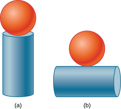
Express your answers in a coordinate system that has the origin at the center of the cylinder.
Glossary
- center of mass
- weighted average position of the mass
- external force
- force applied to an extended object that changes the momentum of the extended object as a whole
- internal force
- force that the simple particles that make up an extended object exert on each other. Internal forces can be attractive or repulsive
- linear mass density
- [latex]\lambda[/latex], expressed as the number of kilograms of material per meter