
14 Fluid Mechanics
14.3 Pascal’s Principle and Hydraulics
Learning Objectives
By the end of this section, you will be able to:
- State Pascal’s principle
- Describe applications of Pascal’s principle
- Derive relationships between forces in a hydraulic system
In 1653, the French philosopher and scientist Blaise Pascal published his Treatise on the Equilibrium of Liquids, in which he discussed principles of static fluids. A static fluid is a fluid that is not in motion. When a fluid is not flowing, we say that the fluid is in static equilibrium. If the fluid is water, we say it is in hydrostatic equilibrium. For a fluid in static equilibrium, the net force on any part of the fluid must be zero; otherwise the fluid will start to flow.
Pascal’s observations—since proven experimentally—provide the foundation for hydraulics, one of the most important developments in modern mechanical technology. Pascal observed that a change in pressure applied to an enclosed fluid is transmitted undiminished throughout the fluid and to the walls of its container. Because of this, we often know more about pressure than other physical quantities in fluids. Moreover, Pascal’s principle implies that the total pressure in a fluid is the sum of the pressures from different sources. A good example is the fluid at a depth depends on the depth of the fluid and the pressure of the atmosphere.
Pascal’s Principle
Pascal’s principle (also known as Pascal’s law) states that when a change in pressure is applied to an enclosed fluid, it is transmitted undiminished to all portions of the fluid and to the walls of its container. In an enclosed fluid, since atoms of the fluid are free to move about, they transmit pressure to all parts of the fluid and to the walls of the container. Any change in pressure is transmitted undiminished.
Note that this principle does not say that the pressure is the same at all points of a fluid—which is not true, since the pressure in a fluid near Earth varies with height. Rather, this principle applies to the change in pressure. Suppose you place some water in a cylindrical container of height H and cross-sectional area A that has a movable piston of mass m (Figure). Adding weight Mg at the top of the piston increases the pressure at the top by Mg/A, since the additional weight also acts over area A of the lid:
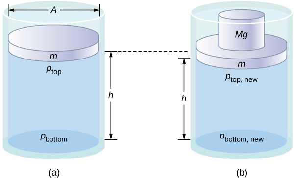
According to Pascal’s principle, the pressure at all points in the water changes by the same amount, Mg/A. Thus, the pressure at the bottom also increases by Mg/A. The pressure at the bottom of the container is equal to the sum of the atmospheric pressure, the pressure due the fluid, and the pressure supplied by the mass. The change in pressure at the bottom of the container due to the mass is
Since the pressure changes are the same everywhere in the fluid, we no longer need subscripts to designate the pressure change for top or bottom:
Pascal’s Barrel is a great demonstration of Pascal’s principle. Watch a simulation of Pascal’s 1646 experiment, in which he demonstrated the effects of changing pressure in a fluid.
Applications of Pascal’s Principle and Hydraulic Systems
Hydraulic systems are used to operate automotive brakes, hydraulic jacks, and numerous other mechanical systems (Figure).
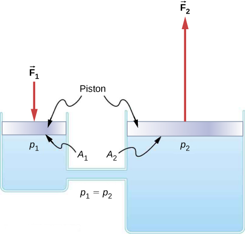
We can derive a relationship between the forces in this simple hydraulic system by applying Pascal’s principle. Note first that the two pistons in the system are at the same height, so there is no difference in pressure due to a difference in depth. The pressure due to [latex]{F}_{1}[/latex] acting on area [latex]{A}_{1}[/latex] is simply
According to Pascal’s principle, this pressure is transmitted undiminished throughout the fluid and to all walls of the container. Thus, a pressure [latex]{p}_{2}[/latex] is felt at the other piston that is equal to [latex]{p}_{1}[/latex]. That is, [latex]{p}_{1}={p}_{2}.[/latex] However, since[latex]{p}_{2}={F}_{2}\text{/}{A}_{2},[/latex] we see that
This equation relates the ratios of force to area in any hydraulic system, provided that the pistons are at the same vertical height and that friction in the system is negligible.
Hydraulic systems can increase or decrease the force applied to them. To make the force larger, the pressure is applied to a larger area. For example, if a 100-N force is applied to the left cylinder in Figure and the right cylinder has an area five times greater, then the output force is 500 N. Hydraulic systems are analogous to simple levers, but they have the advantage that pressure can be sent through tortuously curved lines to several places at once.
The hydraulic jack is such a hydraulic system. A hydraulic jack is used to lift heavy loads, such as the ones used by auto mechanics to raise an automobile. It consists of an incompressible fluid in a U-tube fitted with a movable piston on each side. One side of the U-tube is narrower than the other. A small force applied over a small area can balance a much larger force on the other side over a larger area (Figure).
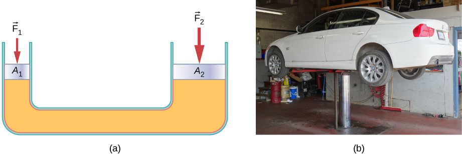
From Pascal’s principle, it can be shown that the force needed to lift the car is less than the weight of the car:
where [latex]{F}_{1}[/latex] is the force applied to lift the car, [latex]{A}_{1}[/latex] is the cross-sectional area of the smaller piston, [latex]{A}_{2}[/latex] is the cross sectional area of the larger piston, and [latex]{F}_{2}[/latex] is the weight of the car.
Example
Calculating Force on Wheel Cylinders: Pascal Puts on the Brakes
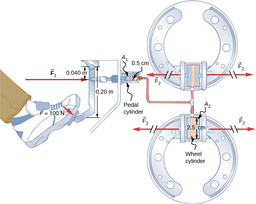
Consider the automobile hydraulic system shown in Figure. Suppose a force of 100 N is applied to the brake pedal, which acts on the pedal cylinder (acting as a “master” cylinder) through a lever. A force of 500 N is exerted on the pedal cylinder. Pressure created in the pedal cylinder is transmitted to the four wheel cylinders. The pedal cylinder has a diameter of 0.500 cm and each wheel cylinder has a diameter of 2.50 cm. Calculate the magnitude of the force [latex]{F}_{2}[/latex] created at each of the wheel cylinders.
Strategy
We are given the force [latex]{F}_{1}[/latex] applied to the pedal cylinder. The cross-sectional areas [latex]{A}_{1}[/latex] and [latex]{A}_{2}[/latex] can be calculated from their given diameters. Then we can use the following relationship to find the force [latex]{F}_{2}[/latex]:
Manipulate this algebraically to get [latex]{F}_{2}[/latex] on one side and substitute known values.
Solution
Pascal’s principle applied to hydraulic systems is given by [latex]\frac{{F}_{1}}{{A}_{1}}=\frac{{F}_{2}}{{A}_{2}}:[/latex]
Significance
This value is the force exerted by each of the four wheel cylinders. Note that we can add as many wheel cylinders as we wish. If each has a 2.50-cm diameter, each will exert [latex]1.25\times {10}^{4}\,\text{N}\text{.}[/latex] A simple hydraulic system, as an example of a simple machine, can increase force but cannot do more work than is done on it. Work is force times distance moved, and the wheel cylinder moves through a smaller distance than the pedal cylinder. Furthermore, the more wheels added, the smaller the distance each one moves. Many hydraulic systems—such as power brakes and those in bulldozers—have a motorized pump that actually does most of the work in the system.
Check Your Understanding
Would a hydraulic press still operate properly if a gas is used instead of a liquid?
Show Solution
Yes, it would still work, but since a gas is compressible, it would not operate as efficiently. When the force is applied, the gas would first compress and warm. Hence, the air in the brake lines must be bled out in order for the brakes to work properly.
Summary
- Pressure is force per unit area.
- A change in pressure applied to an enclosed fluid is transmitted undiminished to all portions of the fluid and to the walls of its container.
- A hydraulic system is an enclosed fluid system used to exert forces.
Conceptual Questions
Suppose the master cylinder in a hydraulic system is at a greater height than the cylinder it is controlling. Explain how this will affect the force produced at the cylinder that is being controlled.
Problems
How much pressure is transmitted in the hydraulic system considered in Figure? Express your answer in atmospheres.
Show Solution
251 atm
What force must be exerted on the master cylinder of a hydraulic lift to support the weight of a 2000-kg car (a large car) resting on a second cylinder? The master cylinder has a 2.00-cm diameter and the second cylinder has a 24.0-cm diameter.
A host pours the remnants of several bottles of wine into a jug after a party. The host then inserts a cork with a 2.00-cm diameter into the bottle, placing it in direct contact with the wine. The host is amazed when the host pounds the cork into place and the bottom of the jug (with a 14.0-cm diameter) breaks away. Calculate the extra force exerted against the bottom if he pounded the cork with a 120-N force.
Show Solution
[latex]5.76\times {10}^{3}\,\text{N}\,\text{extra force}[/latex]
A certain hydraulic system is designed to exert a force 100 times as large as the one put into it. (a) What must be the ratio of the area of the cylinder that is being controlled to the area of the master cylinder? (b) What must be the ratio of their diameters? (c) By what factor is the distance through which the output force moves reduced relative to the distance through which the input force moves? Assume no losses due to friction.
Verify that work input equals work output for a hydraulic system assuming no losses due to friction. Do this by showing that the distance the output force moves is reduced by the same factor that the output force is increased. Assume the volume of the fluid is constant. What effect would friction within the fluid and between components in the system have on the output force? How would this depend on whether or not the fluid is moving?
Show Solution
If the system is not moving, the friction would not play a role. With friction, we know there are losses, so that [latex]{W}_{\text{o}}={W}_{\text{i}}-{W}_{\text{f}};[/latex] therefore, the work output is less than the work input. In other words, to account for friction, you would need to push harder on the input piston than was calculated.
Glossary
- hydraulic jack
- simple machine that uses cylinders of different diameters to distribute force
- hydrostatic equilibrium
- state at which water is not flowing, or is static
- Pascal’s principle
- change in pressure applied to an enclosed fluid is transmitted undiminished to all portions of the fluid and to the walls of its container