
6 Applications of Newton’s Laws
6.3 Centripetal Force
Learning Objectives
By the end of the section, you will be able to:
- Explain the equation for centripetal acceleration
- Apply Newton’s second law to develop the equation for centripetal force
- Use circular motion concepts in solving problems involving Newton’s laws of motion
In Motion in Two and Three Dimensions, we examined the basic concepts of circular motion. An object undergoing circular motion, like one of the race cars shown at the beginning of this chapter, must be accelerating because it is changing the direction of its velocity. We proved that this centrally directed acceleration, called centripetal acceleration, is given by the formula
where v is the velocity of the object, directed along a tangent line to the curve at any instant. If we know the angular velocity [latex]\omega[/latex], then we can use
Angular velocity gives the rate at which the object is turning through the curve, in units of rad/s. This acceleration acts along the radius of the curved path and is thus also referred to as a radial acceleration.
An acceleration must be produced by a force. Any force or combination of forces can cause a centripetal or radial acceleration. Just a few examples are the tension in the rope on a tether ball, the force of Earth’s gravity on the Moon, friction between roller skates and a rink floor, a banked roadway’s force on a car, and forces on the tube of a spinning centrifuge. Any net force causing uniform circular motion is called a centripetal force. The direction of a centripetal force is toward the center of curvature, the same as the direction of centripetal acceleration. According to Newton’s second law of motion, net force is mass times acceleration: [latex]{F}_{\text{net}}=ma.[/latex] For uniform circular motion, the acceleration is the centripetal acceleration:.[latex]a={a}_{\text{c}}.[/latex] Thus, the magnitude of centripetal force [latex]{F}_{\text{c}}[/latex] is
By substituting the expressions for centripetal acceleration [latex]{a}_{\text{c}}[/latex] [latex]({a}_{\text{c}}=\frac{{v}^{2}}{r};{a}_{\text{c}}=r{\omega }^{2}),[/latex] we get two expressions for the centripetal force [latex]{F}_{\text{c}}[/latex] in terms of mass, velocity, angular velocity, and radius of curvature:
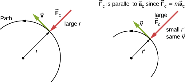
You may use whichever expression for centripetal force is more convenient. Centripetal force [latex]{\mathbf{\overset{\to }{F}}}_{\text{c}}[/latex] is always perpendicular to the path and points to the center of curvature, because [latex]{\mathbf{\overset{\to }{a}}}_{\text{c}}[/latex] is perpendicular to the velocity and points to the center of curvature. Note that if you solve the first expression for r, you get
This implies that for a given mass and velocity, a large centripetal force causes a small radius of curvature—that is, a tight curve, as in Figure.
Example
What Coefficient of Friction Do Cars Need on a Flat Curve?
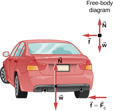
(a) Calculate the centripetal force exerted on a 900.0-kg car that negotiates a 500.0-m radius curve at 25.00 m/s. (b) Assuming an unbanked curve, find the minimum static coefficient of friction between the tires and the road, static friction being the reason that keeps the car from slipping (Figure).
Strategy
- We know that [latex]{F}_{\text{c}}=\frac{m{v}^{2}}{r}.[/latex] Thus,
[latex]{F}_{\text{c}}=\frac{m{v}^{2}}{r}=\frac{(900.0\,\text{kg}){(25.00\,\text{m/s})}^{2}}{(500.0\,\text{m})}=1125\,\text{N}\text{.}[/latex]
- Figure shows the forces acting on the car on an unbanked (level ground) curve. Friction is to the left, keeping the car from slipping, and because it is the only horizontal force acting on the car, the friction is the centripetal force in this case. We know that the maximum static friction (at which the tires roll but do not slip) is [latex]{\mu }_{\text{s}}N,[/latex] where [latex]{\mu }_{\text{s}}[/latex] is the static coefficient of friction and N is the normal force. The normal force equals the car’s weight on level ground, so [latex]N=mg.[/latex] Thus the centripetal force in this situation is
[latex]{F}_{\text{c}}\equiv f={\mu }_{\text{s}}N={\mu }_{\text{s}}mg.[/latex]
Now we have a relationship between centripetal force and the coefficient of friction. Using the equation
[latex]{F}_{\text{c}}=m\frac{{v}^{2}}{r},[/latex]we obtain
[latex]m\frac{{v}^{2}}{r}={\mu }_{\text{s}}mg.[/latex]We solve this for [latex]{\mu }_{\text{s}},[/latex] noting that mass cancels, and obtain
[latex]{\mu }_{\text{s}}=\frac{{v}^{2}}{rg}.[/latex]Substituting the knowns,
[latex]{\mu }_{\text{s}}=\frac{{(25.00\,\text{m/s})}^{2}}{(500.0\,\text{m})(9.80\,{\text{m/s}}^{2})}=0.13.[/latex](Because coefficients of friction are approximate, the answer is given to only two digits.)
Significance
The coefficient of friction found in Figure(b) is much smaller than is typically found between tires and roads. The car still negotiates the curve if the coefficient is greater than 0.13, because static friction is a responsive force, able to assume a value less than but no more than [latex]{\mu }_{\text{s}}N.[/latex] A higher coefficient would also allow the car to negotiate the curve at a higher speed, but if the coefficient of friction is less, the safe speed would be less than 25 m/s. Note that mass cancels, implying that, in this example, it does not matter how heavily loaded the car is to negotiate the turn. Mass cancels because friction is assumed proportional to the normal force, which in turn is proportional to mass. If the surface of the road were banked, the normal force would be less, as discussed next.
Check Your Understanding
A car moving at 96.8 km/h travels around a circular curve of radius 182.9 m on a flat country road. What must be the minimum coefficient of static friction to keep the car from slipping?
Show Solution
0.40
Banked Curves
Let us now consider banked curves, where the slope of the road helps you negotiate the curve (Figure). The greater the angle [latex]\theta[/latex], the faster you can take the curve. Race tracks for bikes as well as cars, for example, often have steeply banked curves. In an “ideally banked curve,” the angle [latex]\theta[/latex] is such that you can negotiate the curve at a certain speed without the aid of friction between the tires and the road. We will derive an expression for [latex]\theta[/latex] for an ideally banked curve and consider an example related to it.
For ideal banking, the net external force equals the horizontal centripetal force in the absence of friction. The components of the normal force N in the horizontal and vertical directions must equal the centripetal force and the weight of the car, respectively. In cases in which forces are not parallel, it is most convenient to consider components along perpendicular axes—in this case, the vertical and horizontal directions.
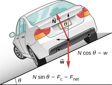
Figure shows a free-body diagram for a car on a frictionless banked curve. If the angle [latex]\theta[/latex] is ideal for the speed and radius, then the net external force equals the necessary centripetal force. The only two external forces acting on the car are its weight [latex]\mathbf{\overset{\to }{w}}[/latex] and the normal force of the road [latex]\mathbf{\overset{\to }{N}}.[/latex] (A frictionless surface can only exert a force perpendicular to the surface—that is, a normal force.) These two forces must add to give a net external force that is horizontal toward the center of curvature and has magnitude [latex]m{v}^{2}\text{/}r.[/latex] Because this is the crucial force and it is horizontal, we use a coordinate system with vertical and horizontal axes. Only the normal force has a horizontal component, so this must equal the centripetal force, that is,
Because the car does not leave the surface of the road, the net vertical force must be zero, meaning that the vertical components of the two external forces must be equal in magnitude and opposite in direction. From Figure, we see that the vertical component of the normal force is [latex]N\,\text{cos}\,\theta ,[/latex] and the only other vertical force is the car’s weight. These must be equal in magnitude; thus,
Now we can combine these two equations to eliminate N and get an expression for [latex]\theta[/latex], as desired. Solving the second equation for [latex]N=mg\text{/}(cos\theta )[/latex] and substituting this into the first yields
Taking the inverse tangent gives
This expression can be understood by considering how [latex]\theta[/latex] depends on v and r. A large [latex]\theta[/latex] is obtained for a large v and a small r. That is, roads must be steeply banked for high speeds and sharp curves. Friction helps, because it allows you to take the curve at greater or lower speed than if the curve were frictionless. Note that [latex]\theta[/latex] does not depend on the mass of the vehicle.
Example
What Is the Ideal Speed to Take a Steeply Banked Tight Curve?
Curves on some test tracks and race courses, such as Daytona International Speedway in Florida, are very steeply banked. This banking, with the aid of tire friction and very stable car configurations, allows the curves to be taken at very high speed. To illustrate, calculate the speed at which a 100.0-m radius curve banked at [latex]31.0^\circ[/latex] should be driven if the road were frictionless.
Strategy
We first note that all terms in the expression for the ideal angle of a banked curve except for speed are known; thus, we need only rearrange it so that speed appears on the left-hand side and then substitute known quantities.
Solution
Starting with
we get
Noting that [latex]\text{tan}\,31.0^\circ=0.609,[/latex] we obtain
Significance
This is just about 165 km/h, consistent with a very steeply banked and rather sharp curve. Tire friction enables a vehicle to take the curve at significantly higher speeds.
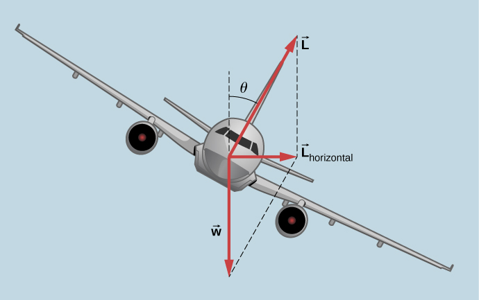
Airplanes also make turns by banking. The lift force, due to the force of the air on the wing, acts at right angles to the wing. When the airplane banks, the pilot is obtaining greater lift than necessary for level flight. The vertical component of lift balances the airplane’s weight, and the horizontal component accelerates the plane. The banking angle shown in Figure is given by [latex]\theta[/latex]. We analyze the forces in the same way we treat the case of the car rounding a banked curve.
Join the ladybug in an exploration of rotational motion. Rotate the merry-go-round to change its angle or choose a constant angular velocity or angular acceleration. Explore how circular motion relates to the bug’s xy-position, velocity, and acceleration using vectors or graphs.
A circular motion requires a force, the so-called centripetal force, which is directed to the axis of rotation. This simplified model of a carousel demonstrates this force.
Inertial Forces and Noninertial (Accelerated) Frames: The Coriolis Force
What do taking off in a jet airplane, turning a corner in a car, riding a merry-go-round, and the circular motion of a tropical cyclone have in common? Each exhibits inertial forces—forces that merely seem to arise from motion, because the observer’s frame of reference is accelerating or rotating. When taking off in a jet, most people would agree it feels as if you are being pushed back into the seat as the airplane accelerates down the runway. Yet a physicist would say that you tend to remain stationary while the seat pushes forward on you. An even more common experience occurs when you make a tight curve in your car—say, to the right (Figure). You feel as if you are thrown (that is, forced) toward the left relative to the car. Again, a physicist would say that you are going in a straight line (recall Newton’s first law) but the car moves to the right, not that you are experiencing a force from the left.
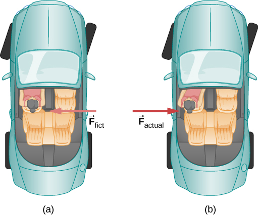
We can reconcile these points of view by examining the frames of reference used. Let us concentrate on people in a car. Passengers instinctively use the car as a frame of reference, whereas a physicist might use Earth. The physicist might make this choice because Earth is nearly an inertial frame of reference, in which all forces have an identifiable physical origin. In such a frame of reference, Newton’s laws of motion take the form given in Newton’s Laws of Motion. The car is a noninertial frame of reference because it is accelerated to the side. The force to the left sensed by car passengers is an inertial force having no physical origin (it is due purely to the inertia of the passenger, not to some physical cause such as tension, friction, or gravitation). The car, as well as the driver, is actually accelerating to the right. This inertial force is said to be an inertial force because it does not have a physical origin, such as gravity.
A physicist will choose whatever reference frame is most convenient for the situation being analyzed. There is no problem to a physicist in including inertial forces and Newton’s second law, as usual, if that is more convenient, for example, on a merry-go-round or on a rotating planet. Noninertial (accelerated) frames of reference are used when it is useful to do so. Different frames of reference must be considered in discussing the motion of an astronaut in a spacecraft traveling at speeds near the speed of light, as you will appreciate in the study of the special theory of relativity.
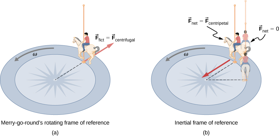
Let us now take a mental ride on a merry-go-round—specifically, a rapidly rotating playground merry-go-round (Figure). You take the merry-go-round to be your frame of reference because you rotate together. When rotating in that noninertial frame of reference, you feel an inertial force that tends to throw you off; this is often referred to as a centrifugal force (not to be confused with centripetal force). Centrifugal force is a commonly used term, but it does not actually exist. You must hang on tightly to counteract your inertia (which people often refer to as centrifugal force). In Earth’s frame of reference, there is no force trying to throw you off; we emphasize that centrifugal force is a fiction. You must hang on to make yourself go in a circle because otherwise you would go in a straight line, right off the merry-go-round, in keeping with Newton’s first law. But the force you exert acts toward the center of the circle.
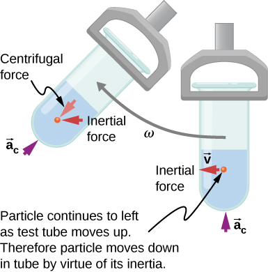
This inertial effect, carrying you away from the center of rotation if there is no centripetal force to cause circular motion, is put to good use in centrifuges (Figure). A centrifuge spins a sample very rapidly, as mentioned earlier in this chapter. Viewed from the rotating frame of reference, the inertial force throws particles outward, hastening their sedimentation. The greater the angular velocity, the greater the centrifugal force. But what really happens is that the inertia of the particles carries them along a line tangent to the circle while the test tube is forced in a circular path by a centripetal force.
Let us now consider what happens if something moves in a rotating frame of reference. For example, what if you slide a ball directly away from the center of the merry-go-round, as shown in Figure? The ball follows a straight path relative to Earth (assuming negligible friction) and a path curved to the right on the merry-go-round’s surface. A person standing next to the merry-go-round sees the ball moving straight and the merry-go-round rotating underneath it. In the merry-go-round’s frame of reference, we explain the apparent curve to the right by using an inertial force, called the Coriolis force, which causes the ball to curve to the right. The Coriolis force can be used by anyone in that frame of reference to explain why objects follow curved paths and allows us to apply Newton’s laws in noninertial frames of reference.

Up until now, we have considered Earth to be an inertial frame of reference with little or no worry about effects due to its rotation. Yet such effects do exist—in the rotation of weather systems, for example. Most consequences of Earth’s rotation can be qualitatively understood by analogy with the merry-go-round. Viewed from above the North Pole, Earth rotates counterclockwise, as does the merry-go-round in Figure. As on the merry-go-round, any motion in Earth’s Northern Hemisphere experiences a Coriolis force to the right. Just the opposite occurs in the Southern Hemisphere; there, the force is to the left. Because Earth’s angular velocity is small, the Coriolis force is usually negligible, but for large-scale motions, such as wind patterns, it has substantial effects.
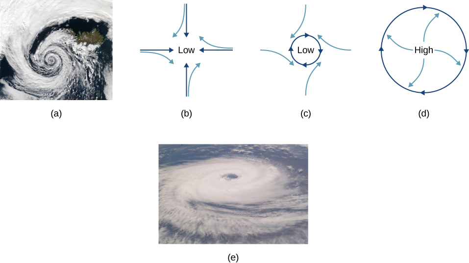
The Coriolis force causes hurricanes in the Northern Hemisphere to rotate in the counterclockwise direction, whereas tropical cyclones in the Southern Hemisphere rotate in the clockwise direction. (The terms hurricane, typhoon, and tropical storm are regionally specific names for cyclones, which are storm systems characterized by low pressure centers, strong winds, and heavy rains.) Figure helps show how these rotations take place. Air flows toward any region of low pressure, and tropical cyclones contain particularly low pressures. Thus winds flow toward the center of a tropical cyclone or a low-pressure weather system at the surface. In the Northern Hemisphere, these inward winds are deflected to the right, as shown in the figure, producing a counterclockwise circulation at the surface for low-pressure zones of any type. Low pressure at the surface is associated with rising air, which also produces cooling and cloud formation, making low-pressure patterns quite visible from space. Conversely, wind circulation around high-pressure zones is clockwise in the Southern Hemisphere but is less visible because high pressure is associated with sinking air, producing clear skies.
The rotation of tropical cyclones and the path of a ball on a merry-go-round can just as well be explained by inertia and the rotation of the system underneath. When noninertial frames are used, inertial forces, such as the Coriolis force, must be invented to explain the curved path. There is no identifiable physical source for these inertial forces. In an inertial frame, inertia explains the path, and no force is found to be without an identifiable source. Either view allows us to describe nature, but a view in an inertial frame is the simplest in the sense that all forces have origins and explanations.
Summary
- Centripetal force [latex]{\mathbf{\overset{\to }{F}}}_{\text{c}}[/latex] is a “center-seeking” force that always points toward the center of rotation. It is perpendicular to linear velocity and has the magnitude
[latex]{F}_{\text{c}}=m{a}_{\text{c}}.[/latex]
- Rotating and accelerated frames of reference are noninertial. Inertial forces, such as the Coriolis force, are needed to explain motion in such frames.
Conceptual Questions
If you wish to reduce the stress (which is related to centripetal force) on high-speed tires, would you use large- or small-diameter tires? Explain.
Define centripetal force. Can any type of force (for example, tension, gravitational force, friction, and so on) be a centripetal force? Can any combination of forces be a centripetal force?
Show Solution
Centripetal force is defined as any net force causing uniform circular motion. The centripetal force is not a new kind of force. The label “centripetal” refers to any force that keeps something turning in a circle. That force could be tension, gravity, friction, electrical attraction, the normal force, or any other force. Any combination of these could be the source of centripetal force, for example, the centripetal force at the top of the path of a tetherball swung through a vertical circle is the result of both tension and gravity.
If centripetal force is directed toward the center, why do you feel that you are ‘thrown’ away from the center as a car goes around a curve? Explain.
Race car drivers routinely cut corners, as shown below (Path 2). Explain how this allows the curve to be taken at the greatest speed.
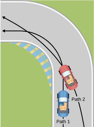
Show Solution
The driver who cuts the corner (on Path 2) has a more gradual curve, with a larger radius. That one will be the better racing line. If the driver goes too fast around a corner using a racing line, he will still slide off the track; the key is to stay at the maximum value of static friction. So, the driver wants maximum possible speed and maximum friction. Consider the equation for centripetal force: [latex]{F}_{\text{c}}=m\frac{{v}^{2}}{r}[/latex] where v is speed and r is the radius of curvature. So by decreasing the curvature (1/r) of the path that the car takes, we reduce the amount of force the tires have to exert on the road, meaning we can now increase the speed, v. Looking at this from the point of view of the driver on Path 1, we can reason this way: the sharper the turn, the smaller the turning circle; the smaller the turning circle, the larger is the required centripetal force. If this centripetal force is not exerted, the result is a skid.
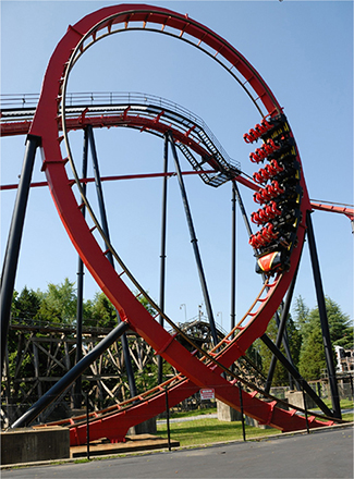
Many amusement parks have rides that make vertical loops like the one shown below. For safety, the cars are attached to the rails in such a way that they cannot fall off. If the car goes over the top at just the right speed, gravity alone will supply the centripetal force. What other force acts and what is its direction if:
(a) The car goes over the top at faster than this speed?
(b) The car goes over the top at slower than this speed?
What causes water to be removed from clothes in a spin-dryer?
Show Solution
The barrel of the dryer provides a centripetal force on the clothes (including the water droplets) to keep them moving in a circular path. As a water droplet comes to one of the holes in the barrel, it will move in a path tangent to the circle.
As a skater forms a circle, what force is responsible for making his turn? Use a free-body diagram in your answer.
Suppose a child is riding on a merry-go-round at a distance about halfway between its center and edge. She has a lunch box resting on wax paper, so that there is very little friction between it and the merry-go-round. Which path shown below will the lunch box take when she lets go? The lunch box leaves a trail in the dust on the merry-go-round. Is that trail straight, curved to the left, or curved to the right? Explain your answer.
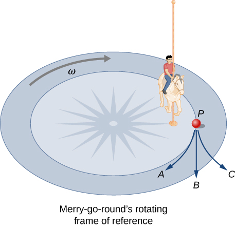
Show Solution
If there is no friction, then there is no centripetal force. This means that the lunch box will move along a path tangent to the circle, and thus follows path B. The dust trail will be straight. This is a result of Newton’s first law of motion.
Do you feel yourself thrown to either side when you negotiate a curve that is ideally banked for your car’s speed? What is the direction of the force exerted on you by the car seat?
Suppose a mass is moving in a circular path on a frictionless table as shown below. In Earth’s frame of reference, there is no centrifugal force pulling the mass away from the center of rotation, yet there is a force stretching the string attaching the mass to the nail. Using concepts related to centripetal force and Newton’s third law, explain what force stretches the string, identifying its physical origin.
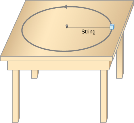
Show Solution
There must be a centripetal force to maintain the circular motion; this is provided by the nail at the center. Newton’s third law explains the phenomenon. The action force is the force of the string on the mass; the reaction force is the force of the mass on the string. This reaction force causes the string to stretch.
When a toilet is flushed or a sink is drained, the water (and other material) begins to rotate about the drain on the way down. Assuming no initial rotation and a flow initially directly straight toward the drain, explain what causes the rotation and which direction it has in the Northern Hemisphere. (Note that this is a small effect and in most toilets the rotation is caused by directional water jets.) Would the direction of rotation reverse if water were forced up the drain?
A car rounds a curve and encounters a patch of ice with a very low coefficient of kinetic fiction. The car slides off the road. Describe the path of the car as it leaves the road.
Show Solution
Since the radial friction with the tires supplies the centripetal force, and friction is nearly 0 when the car encounters the ice, the car will obey Newton’s first law and go off the road in a straight line path, tangent to the curve. A common misconception is that the car will follow a curved path off the road.
In one amusement park ride, riders enter a large vertical barrel and stand against the wall on its horizontal floor. The barrel is spun up and the floor drops away. Riders feel as if they are pinned to the wall by a force something like the gravitational force. This is an inertial force sensed and used by the riders to explain events in the rotating frame of reference of the barrel. Explain in an inertial frame of reference (Earth is nearly one) what pins the riders to the wall, and identify all forces acting on them.
Two friends are having a conversation. Anna says a satellite in orbit is in free fall because the satellite keeps falling toward Earth. Tom says a satellite in orbit is not in free fall because the acceleration due to gravity is not [latex]9.80\,{\text{m/s}}^{2}[/latex]. Who do you agree with and why?
Show Solution
Anna is correct. The satellite is freely falling toward Earth due to gravity, even though gravity is weaker at the altitude of the satellite, and g is not [latex]9.80\,{\text{m/s}}^{2}[/latex]. Free fall does not depend on the value of g; that is, you could experience free fall on Mars if you jumped off Olympus Mons (the tallest volcano in the solar system).
A nonrotating frame of reference placed at the center of the Sun is very nearly an inertial one. Why is it not exactly an inertial frame?
Problems
(a) A 22.0-kg child is riding a playground merry-go-round that is rotating at 40.0 rev/min. What centripetal force is exerted if he is 1.25 m from its center? (b) What centripetal force is exerted if the merry-go-round rotates at 3.00 rev/min and he is 8.00 m from its center? (c) Compare each force with his weight.
Show Solution
a. 483 N; b. 17.4 N; c. 2.24, 0.0807
Calculate the centripetal force on the end of a 100-m (radius) wind turbine blade that is rotating at 0.5 rev/s. Assume the mass is 4 kg.
What is the ideal banking angle for a gentle turn of 1.20-km radius on a highway with a 105 km/h speed limit (about 65 mi/h), assuming everyone travels at the limit?
Show Solution
[latex]4.14^\circ[/latex]
What is the ideal speed to take a 100.0-m-radius curve banked at a [latex]20.0^\circ[/latex] angle?
(a) What is the radius of a bobsled turn banked at [latex]75.0^\circ[/latex] and taken at 30.0 m/s, assuming it is ideally banked? (b) Calculate the centripetal acceleration. (c) Does this acceleration seem large to you?
Show Solution
a. 24.6 m; b. [latex]36.6\,{\text{m/s}}^{2};[/latex] c. 3.73 times g
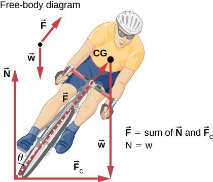
Part of riding a bicycle involves leaning at the correct angle when making a turn, as seen below. To be stable, the force exerted by the ground must be on a line going through the center of gravity. The force on the bicycle wheel can be resolved into two perpendicular components—friction parallel to the road (this must supply the centripetal force) and the vertical normal force (which must equal the system’s weight). (a) Show that [latex]\theta[/latex] (as defined as shown) is related to the speed v and radius of curvature r of the turn in the same way as for an ideally banked roadway—that is, [latex]\theta ={\text{tan}}^{-1}({v}^{2}\text{/}rg).[/latex] (b) Calculate [latex]\theta[/latex] for a 12.0-m/s turn of radius 30.0 m (as in a race).
If a car takes a banked curve at less than the ideal speed, friction is needed to keep it from sliding toward the inside of the curve (a problem on icy mountain roads). (a) Calculate the ideal speed to take a 100.0 m radius curve banked at [latex]15.0^\circ[/latex]. (b) What is the minimum coefficient of friction needed for a frightened driver to take the same curve at 20.0 km/h?
Show Solution
a. 16.2 m/s; b. 0.234
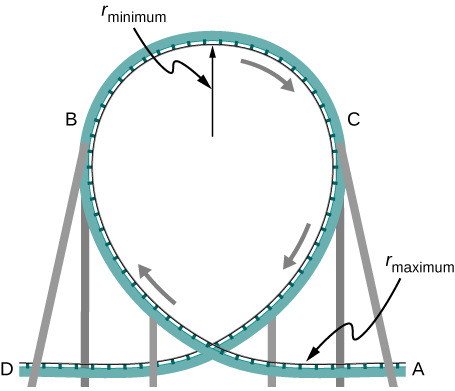
Modern roller coasters have vertical loops like the one shown here. The radius of curvature is smaller at the top than on the sides so that the downward centripetal acceleration at the top will be greater than the acceleration due to gravity, keeping the passengers pressed firmly into their seats. (a) What is the speed of the roller coaster at the top of the loop if the radius of curvature there is 15.0 m and the downward acceleration of the car is 1.50 g? (b) How high above the top of the loop must the roller coaster start from rest, assuming negligible friction? (c) If it actually starts 5.00 m higher than your answer to (b), how much energy did it lose to friction? Its mass is [latex]1.50\times {10}^{3}\,\text{kg}[/latex].
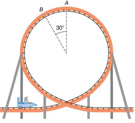
A child of mass 40.0 kg is in a roller coaster car that travels in a loop of radius 7.00 m. At point A the speed of the car is 10.0 m/s, and at point B, the speed is 10.5 m/s. Assume the child is not holding on and does not wear a seat belt. (a) What is the force of the car seat on the child at point A? (b) What is the force of the car seat on the child at point B? (c) What minimum speed is required to keep the child in his seat at point A?
Show Solution
a. 179 N; b. 290 N; c. 8.3 m/s
In the simple Bohr model of the ground state of the hydrogen atom, the electron travels in a circular orbit around a fixed proton. The radius of the orbit is [latex]5.28\times {10}^{-11}\,\text{m,}[/latex] and the speed of the electron is [latex]2.18\times {10}^{6}\,\text{m}\text{/}\text{s}.[/latex] The mass of an electron is [latex]9.11\times {10}^{-31}\,\text{kg}[/latex]. What is the force on the electron?
Railroad tracks follow a circular curve of radius 500.0 m and are banked at an angle of [latex]5.0^\circ[/latex]. For trains of what speed are these tracks designed?
Show Solution
20.7 m/s
The CERN particle accelerator is circular with a circumference of 7.0 km. (a) What is the acceleration of the protons [latex](m=1.67\times {10}^{-27}\,\text{kg})[/latex] that move around the accelerator at [latex]5%[/latex] of the speed of light? (The speed of light is [latex]v=3.00\times {10}^{8}\,\text{m/s}\text{.}[/latex]) (b) What is the force on the protons?
A car rounds an unbanked curve of radius 65 m. If the coefficient of static friction between the road and car is 0.70, what is the maximum speed at which the car traverse the curve without slipping?
Show Solution
21 m/s
A banked highway is designed for traffic moving at 90.0 km/h. The radius of the curve is 310 m. What is the angle of banking of the highway?
Glossary
- banked curve
- curve in a road that is sloping in a manner that helps a vehicle negotiate the curve
- centripetal force
- any net force causing uniform circular motion
- Coriolis force
- inertial force causing the apparent deflection of moving objects when viewed in a rotating frame of reference
- ideal banking
- sloping of a curve in a road, where the angle of the slope allows the vehicle to negotiate the curve at a certain speed without the aid of friction between the tires and the road; the net external force on the vehicle equals the horizontal centripetal force in the absence of friction
- inertial force
- force that has no physical origin
- noninertial frame of reference
- accelerated frame of reference