
11 Angular Momentum
11.1 Rolling Motion
Learning Objectives
By the end of this section, you will be able to:
- Describe the physics of rolling motion without slipping
- Explain how linear variables are related to angular variables for the case of rolling motion without slipping
- Find the linear and angular accelerations in rolling motion with and without slipping
- Calculate the static friction force associated with rolling motion without slipping
- Use energy conservation to analyze rolling motion
Rolling motion is that common combination of rotational and translational motion that we see everywhere, every day. Think about the different situations of wheels moving on a car along a highway, or wheels on a plane landing on a runway, or wheels on a robotic explorer on another planet. Understanding the forces and torques involved in rolling motion is a crucial factor in many different types of situations.
For analyzing rolling motion in this chapter, refer to Figure in Fixed-Axis Rotation to find moments of inertia of some common geometrical objects. You may also find it useful in other calculations involving rotation.
Rolling Motion without Slipping
People have observed rolling motion without slipping ever since the invention of the wheel. For example, we can look at the interaction of a car’s tires and the surface of the road. If the driver depresses the accelerator to the floor, such that the tires spin without the car moving forward, there must be kinetic friction between the wheels and the surface of the road. If the driver depresses the accelerator slowly, causing the car to move forward, then the tires roll without slipping. It is surprising to most people that, in fact, the bottom of the wheel is at rest with respect to the ground, indicating there must be static friction between the tires and the road surface. In Figure, the bicycle is in motion with the rider staying upright. The tires have contact with the road surface, and, even though they are rolling, the bottoms of the tires deform slightly, do not slip, and are at rest with respect to the road surface for a measurable amount of time. There must be static friction between the tire and the road surface for this to be so.

To analyze rolling without slipping, we first derive the linear variables of velocity and acceleration of the center of mass of the wheel in terms of the angular variables that describe the wheel’s motion. The situation is shown in Figure.
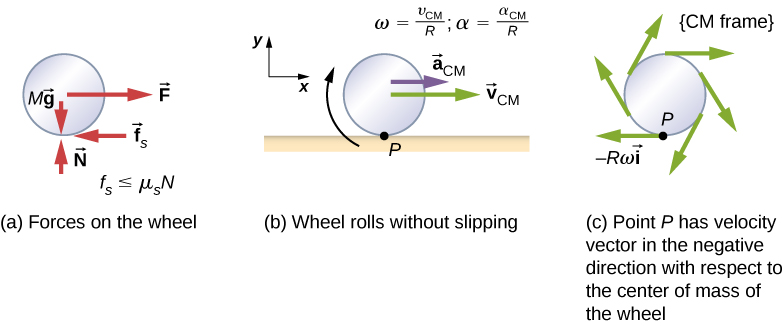
From Figure(a), we see the force vectors involved in preventing the wheel from slipping. In (b), point P that touches the surface is at rest relative to the surface. Relative to the center of mass, point P has velocity [latex]\text{−}R\omega \mathbf{\hat{i}}[/latex], where R is the radius of the wheel and [latex]\omega[/latex] is the wheel’s angular velocity about its axis. Since the wheel is rolling, the velocity of P with respect to the surface is its velocity with respect to the center of mass plus the velocity of the center of mass with respect to the surface:
Since the velocity of P relative to the surface is zero, [latex]{v}_{P}=0[/latex], this says that
Thus, the velocity of the wheel’s center of mass is its radius times the angular velocity about its axis. We show the correspondence of the linear variable on the left side of the equation with the angular variable on the right side of the equation. This is done below for the linear acceleration.
If we differentiate Figure on the left side of the equation, we obtain an expression for the linear acceleration of the center of mass. On the right side of the equation, R is a constant and since [latex]\alpha =\frac{d\omega }{dt},[/latex] we have
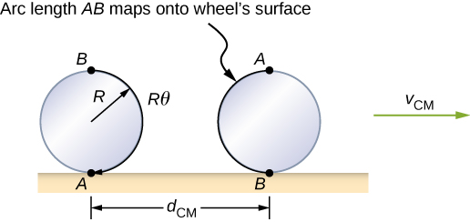
Furthermore, we can find the distance the wheel travels in terms of angular variables by referring to Figure. As the wheel rolls from point A to point B, its outer surface maps onto the ground by exactly the distance travelled, which is [latex]{d}_{\text{CM}}.[/latex] We see from Figure that the length of the outer surface that maps onto the ground is the arc length [latex]R\theta \text{}[/latex]. Equating the two distances, we obtain
Example
Rolling Down an Inclined Plane
A solid cylinder rolls down an inclined plane without slipping, starting from rest. It has mass m and radius r. (a) What is its acceleration? (b) What condition must the coefficient of static friction [latex]{\mu }_{\text{S}}[/latex] satisfy so the cylinder does not slip?
Strategy
Draw a sketch and free-body diagram, and choose a coordinate system. We put x in the direction down the plane and y upward perpendicular to the plane. Identify the forces involved. These are the normal force, the force of gravity, and the force due to friction. Write down Newton’s laws in the x– and y-directions, and Newton’s law for rotation, and then solve for the acceleration and force due to friction.
Solution
- The free-body diagram and sketch are shown in Figure, including the normal force, components of the weight, and the static friction force. There is barely enough friction to keep the cylinder rolling without slipping. Since there is no slipping, the magnitude of the friction force is less than or equal to [latex]{\mu }_{S}N[/latex]. Writing down Newton’s laws in the x– and y-directions, we have
[latex]\sum {F}_{x}=m{a}_{x};\enspace\sum {F}_{y}=m{a}_{y}.[/latex]
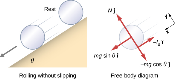
Figure 11.5 A solid cylinder rolls down an inclined plane without slipping from rest. The coordinate system has x in the direction down the inclined plane and y perpendicular to the plane. The free-body diagram is shown with the normal force, the static friction force, and the components of the weight [latex]m\mathbf{\overset{\to }{g}}[/latex]. Friction makes the cylinder roll down the plane rather than slip. Substituting in from the free-body diagram,
[latex]\begin{array}{ccc}\hfill mg\,\text{sin}\,\theta -{f}_{\text{S}}& =\hfill & m{({a}_{\text{CM}})}_{x},\hfill \\ \hfill N-mg\,\text{cos}\,\theta & =\hfill & 0,\hfill \\ \hfill {f}_{\text{S}}& \le \hfill & {\mu }_{\text{S}}N,\hfill \end{array}[/latex]we can then solve for the linear acceleration of the center of mass from these equations:
[latex]{({a}_{\text{CM}})}_{x}=g(\text{sin}\,\theta -{\mu }_{S}\text{cos}\,\theta ).[/latex]However, it is useful to express the linear acceleration in terms of the moment of inertia. For this, we write down Newton’s second law for rotation,
[latex]\sum {\tau }_{\text{CM}}={I}_{\text{CM}}\alpha .[/latex]The torques are calculated about the axis through the center of mass of the cylinder. The only nonzero torque is provided by the friction force. We have
[latex]{f}_{\text{S}}r={I}_{\text{CM}}\alpha .[/latex]Finally, the linear acceleration is related to the angular acceleration by
[latex]{({a}_{\text{CM}})}_{x}=r\alpha .[/latex]These equations can be used to solve for [latex]{a}_{\text{CM}},\alpha ,\,\text{and}\,{f}_{\text{S}}[/latex] in terms of the moment of inertia, where we have dropped the x-subscript. We write [latex]{a}_{\text{CM}}[/latex] in terms of the vertical component of gravity and the friction force, and make the following substitutions.
[latex]{a}_{\text{CM}}=g\text{sin}\,\theta -\frac{{f}_{\text{S}}}{m}[/latex][latex]{f}_{\text{S}}=\frac{{I}_{\text{CM}}\alpha }{r}=\frac{{I}_{\text{CM}}{a}_{\text{CM}}}{{r}^{2}}[/latex]From this we obtain
[latex]\begin{array}{cc}\hfill {a}_{\text{CM}}& =g\,\text{sin}\,\theta -\frac{{I}_{\text{CM}}{a}_{\text{CM}}}{m{r}^{2}},\hfill \\ & =\frac{mg\,\text{sin}\,\theta }{m+({I}_{\text{CM}}\text{/}{r}^{2})}.\hfill \end{array}[/latex]Note that this result is independent of the coefficient of static friction, [latex]{\mu }_{\text{S}}[/latex].
Since we have a solid cylinder, from Figure, we have [latex]{I}_{\text{CM}}=m{r}^{2}\text{/}2[/latex] and
[latex]{a}_{\text{CM}}=\frac{mg\,\text{sin}\,\theta }{m+(m{r}^{2}\text{/}2{r}^{2})}=\frac{2}{3}g\,\text{sin}\,\theta .[/latex]Therefore, we have
[latex]\alpha =\frac{{a}_{\text{CM}}}{r}=\frac{2}{3r}g\,\text{sin}\,\theta .[/latex] - Because slipping does not occur, [latex]{f}_{\text{S}}\le {\mu }_{\text{S}}N[/latex]. Solving for the friction force,
[latex]{f}_{\text{S}}={I}_{\text{CM}}\frac{\alpha }{r}={I}_{\text{CM}}\frac{({a}_{\text{CM}})}{{r}^{2}}=\frac{{I}_{\text{CM}}}{{r}^{2}}(\frac{mg\,\text{sin}\,\theta }{m+({I}_{\text{CM}}\text{/}{r}^{2})})=\frac{mg{I}_{\text{CM}}\,\text{sin}\,\theta }{m{r}^{2}+{I}_{\text{CM}}}.[/latex]
Substituting this expression into the condition for no slipping, and noting that [latex]N=mg\,\text{cos}\,\theta[/latex], we have
[latex]\frac{mg{I}_{\text{CM}}\text{sin}\,\theta }{m{r}^{2}+{I}_{\text{CM}}}\le {\mu }_{\text{S}}mg\,\text{cos}\,\theta[/latex]or
[latex]{\mu }_{\text{S}}\ge \frac{\text{tan}\,\theta }{1+(m{r}^{2}\text{/}{I}_{\text{CM}})}.[/latex]For the solid cylinder, this becomes
[latex]{\mu }_{\text{S}}\ge \frac{\text{tan}\,\theta }{1+(2m{r}^{2}\text{/}m{r}^{2})}=\frac{1}{3}\text{tan}\,\theta .[/latex]
Significance
- The linear acceleration is linearly proportional to [latex]\text{sin}\,\theta .[/latex] Thus, the greater the angle of the incline, the greater the linear acceleration, as would be expected. The angular acceleration, however, is linearly proportional to [latex]\text{sin}\,\theta[/latex] and inversely proportional to the radius of the cylinder. Thus, the larger the radius, the smaller the angular acceleration.
- For no slipping to occur, the coefficient of static friction must be greater than or equal to [latex](1\text{/}3)\text{tan}\,\theta[/latex]. Thus, the greater the angle of incline, the greater the coefficient of static friction must be to prevent the cylinder from slipping.
Check Your Understanding
A hollow cylinder is on an incline at an angle of [latex]60^\circ.[/latex] The coefficient of static friction on the surface is [latex]{\mu }_{S}=0.6[/latex]. (a) Does the cylinder roll without slipping? (b) Will a solid cylinder roll without slipping
a. [latex]{\mu }_{\text{S}}\ge \frac{\text{tan}\,\theta }{1+(m{r}^{2}\text{/}{I}_{\text{CM}})}[/latex]; inserting the angle and noting that for a hollow cylinder [latex]{I}_{\text{CM}}=m{r}^{2},[/latex] we have [latex]{\mu }_{\text{S}}\ge \frac{\text{tan}\,60^\circ}{1+(m{r}^{2}\text{/}m{r}^{2})}=\frac{1}{2}\text{tan}\,60^\circ=0.87;[/latex] we are given a value of 0.6 for the coefficient of static friction, which is less than 0.87, so the condition isn’t satisfied and the hollow cylinder will slip; b. The solid cylinder obeys the condition [latex]{\mu }_{\text{S}}\ge \frac{1}{3}\text{tan}\,\theta =\frac{1}{3}\text{tan}\,60^\circ=0.58.[/latex] The value of 0.6 for [latex]{\mu }_{\text{S}}[/latex] satisfies this condition, so the solid cylinder will not slip.Show Answer
It is worthwhile to repeat the equation derived in this example for the acceleration of an object rolling without slipping:
This is a very useful equation for solving problems involving rolling without slipping. Note that the acceleration is less than that for an object sliding down a frictionless plane with no rotation. The acceleration will also be different for two rotating cylinders with different rotational inertias.
Rolling Motion with Slipping
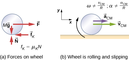
In the case of rolling motion with slipping, we must use the coefficient of kinetic friction, which gives rise to the kinetic friction force since static friction is not present. The situation is shown in Figure. In the case of slipping, [latex]{v}_{\text{CM}}-R\omega \ne 0[/latex], because point P on the wheel is not at rest on the surface, and [latex]{v}_{P}\ne 0[/latex]. Thus, [latex]\omega \ne \frac{{v}_{\text{CM}}}{R},\alpha \ne \frac{{a}_{\text{CM}}}{R}[/latex].
Example
Rolling Down an Inclined Plane with Slipping
A solid cylinder rolls down an inclined plane from rest and undergoes slipping (Figure). It has mass m and radius r. (a) What is its linear acceleration? (b) What is its angular acceleration about an axis through the center of mass?
Strategy
Draw a sketch and free-body diagram showing the forces involved. The free-body diagram is similar to the no-slipping case except for the friction force, which is kinetic instead of static. Use Newton’s second law to solve for the acceleration in the x-direction. Use Newton’s second law of rotation to solve for the angular acceleration.
Solution
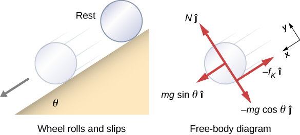
The sum of the forces in the y-direction is zero, so the friction force is now [latex]{f}_{\text{k}}={\mu }_{\text{k}}N={\mu }_{\text{k}}mg\text{cos}\,\theta .[/latex]
Newton’s second law in the x-direction becomes
or
The friction force provides the only torque about the axis through the center of mass, so Newton’s second law of rotation becomes
Solving for [latex]\alpha[/latex], we have
Significance
We write the linear and angular accelerations in terms of the coefficient of kinetic friction. The linear acceleration is the same as that found for an object sliding down an inclined plane with kinetic friction. The angular acceleration about the axis of rotation is linearly proportional to the normal force, which depends on the cosine of the angle of inclination. As [latex]\theta \to 90^\circ[/latex], this force goes to zero, and, thus, the angular acceleration goes to zero.
Conservation of Mechanical Energy in Rolling Motion
In the preceding chapter, we introduced rotational kinetic energy. Any rolling object carries rotational kinetic energy, as well as translational kinetic energy and potential energy if the system requires. Including the gravitational potential energy, the total mechanical energy of an object rolling is
In the absence of any nonconservative forces that would take energy out of the system in the form of heat, the total energy of a rolling object without slipping is conserved and is constant throughout the motion. Examples where energy is not conserved are a rolling object that is slipping, production of heat as a result of kinetic friction, and a rolling object encountering air resistance.
You may ask why a rolling object that is not slipping conserves energy, since the static friction force is nonconservative. The answer can be found by referring back to Figure. Point P in contact with the surface is at rest with respect to the surface. Therefore, its infinitesimal displacement [latex]d\mathbf{\overset{\to }{r}}[/latex] with respect to the surface is zero, and the incremental work done by the static friction force is zero. We can apply energy conservation to our study of rolling motion to bring out some interesting results.
Example
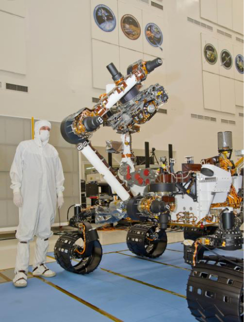
Curiosity Rover
The Curiosity rover, shown in Figure, was deployed on Mars on August 6, 2012. The wheels of the rover have a radius of 25 cm. Suppose astronauts arrive on Mars in the year 2050 and find the now-inoperative Curiosity on the side of a basin. While they are dismantling the rover, an astronaut accidentally loses a grip on one of the wheels, which rolls without slipping down into the bottom of the basin 25 meters below. If the wheel has a mass of 5 kg, what is its velocity at the bottom of the basin?
Strategy
We use mechanical energy conservation to analyze the problem. At the top of the hill, the wheel is at rest and has only potential energy. At the bottom of the basin, the wheel has rotational and translational kinetic energy, which must be equal to the initial potential energy by energy conservation. Since the wheel is rolling without slipping, we use the relation [latex]{v}_{\text{CM}}=r\omega[/latex] to relate the translational variables to the rotational variables in the energy conservation equation. We then solve for the velocity. From Figure, we see that a hollow cylinder is a good approximation for the wheel, so we can use this moment of inertia to simplify the calculation.
Solution
Energy at the top of the basin equals energy at the bottom:
The known quantities are [latex]{I}_{\text{CM}}=m{r}^{2}\text{,}\,r=0.25\,\text{m,}\,\text{and}\,h=25.0\,\text{m}[/latex].
We rewrite the energy conservation equation eliminating [latex]\omega[/latex] by using [latex]\omega =\frac{{v}_{\text{CM}}}{r}.[/latex] We have
or
On Mars, the acceleration of gravity is [latex]3.71\,{\,\text{m/s}}^{2},[/latex] which gives the magnitude of the velocity at the bottom of the basin as
Significance
This is a fairly accurate result considering that Mars has very little atmosphere, and the loss of energy due to air resistance would be minimal. The result also assumes that the terrain is smooth, such that the wheel wouldn’t encounter rocks and bumps along the way.
Also, in this example, the kinetic energy, or energy of motion, is equally shared between linear and rotational motion. If we look at the moments of inertia in Figure, we see that the hollow cylinder has the largest moment of inertia for a given radius and mass. If the wheels of the rover were solid and approximated by solid cylinders, for example, there would be more kinetic energy in linear motion than in rotational motion. This would give the wheel a larger linear velocity than the hollow cylinder approximation. Thus, the solid cylinder would reach the bottom of the basin faster than the hollow cylinder.
Summary
- In rolling motion without slipping, a static friction force is present between the rolling object and the surface. The relations [latex]{v}_{\text{CM}}=R\omega ,{a}_{\text{CM}}=R\alpha ,\,\text{and}\,{d}_{\text{CM}}=R\theta[/latex] all apply, such that the linear velocity, acceleration, and distance of the center of mass are the angular variables multiplied by the radius of the object.
- In rolling motion with slipping, a kinetic friction force arises between the rolling object and the surface. In this case, [latex]{v}_{\text{CM}}\ne R\omega ,{a}_{\text{CM}}\ne R\alpha ,\,\text{and}\,{d}_{\text{CM}}\ne R\theta[/latex].
- Energy conservation can be used to analyze rolling motion. Energy is conserved in rolling motion without slipping. Energy is not conserved in rolling motion with slipping due to the heat generated by kinetic friction.
Conceptual Questions
Can a round object released from rest at the top of a frictionless incline undergo rolling motion?
Show Solution
No, the static friction force is zero.
A cylindrical can of radius R is rolling across a horizontal surface without slipping. (a) After one complete revolution of the can, what is the distance that its center of mass has moved? (b) Would this distance be greater or smaller if slipping occurred?
A wheel is released from the top on an incline. Is the wheel most likely to slip if the incline is steep or gently sloped?
Show Solution
The wheel is more likely to slip on a steep incline since the coefficient of static friction must increase with the angle to keep rolling motion without slipping.
Which rolls down an inclined plane faster, a hollow cylinder or a solid sphere? Both have the same mass and radius.
A hollow sphere and a hollow cylinder of the same radius and mass roll up an incline without slipping and have the same initial center of mass velocity. Which object reaches a greater height before stopping?
Show Solution
The cylinder reaches a greater height. By Figure, its acceleration in the direction down the incline would be less.
Problems
What is the angular velocity of a 75.0-cm-diameter tire on an automobile traveling at 90.0 km/h?
[latex]{v}_{\text{CM}}=R\omega \,\Rightarrow \omega =66.7\,\text{rad/s}[/latex]Show Answer
A boy rides his bicycle 2.00 km. The wheels have radius 30.0 cm. What is the total angle the tires rotate through during his trip?
If the boy on the bicycle in the preceding problem accelerates from rest to a speed of 10.0 m/s in 10.0 s, what is the angular acceleration of the tires?
Show Solution
[latex]\alpha =3.3\,\text{rad}\text{/}{\text{s}}^{2}[/latex]
Formula One race cars have 66-cm-diameter tires. If a Formula One averages a speed of 300 km/h during a race, what is the angular displacement in revolutions of the wheels if the race car maintains this speed for 1.5 hours?
A marble rolls down an incline at [latex]30^\circ[/latex] from rest. (a) What is its acceleration? (b) How far does it go in 3.0 s?
Show Solution
[latex]{I}_{\text{CM}}=\frac{2}{5}m{r}^{2},\,{a}_{\text{CM}}=3.5\,\text{m}\text{/}{\text{s}}^{2};\,x=15.75\,\text{m}[/latex]
Repeat the preceding problem replacing the marble with a solid cylinder. Explain the new result.
A rigid body with a cylindrical cross-section is released from the top of a [latex]30^\circ[/latex] incline. It rolls 10.0 m to the bottom in 2.60 s. Find the moment of inertia of the body in terms of its mass m and radius r.
Show Solution
positive is down the incline plane;
[latex]{a}_{\text{CM}}=\frac{mg\,\text{sin}\,\theta }{m+({I}_{\text{CM}}\text{/}{r}^{2})}\Rightarrow {I}_{\text{CM}}={r}^{2}[\frac{mg\,\text{sin}30}{{a}_{\text{CM}}}-m][/latex],
[latex]x-{x}_{0}={v}_{0}t-\frac{1}{2}{a}_{\text{CM}}{t}^{2}\Rightarrow {a}_{\text{CM}}=2.96\,{\text{m/s}}^{2},[/latex]
[latex]{I}_{\text{CM}}=0.66\,m{r}^{2}[/latex]
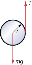
A yo-yo can be thought of a solid cylinder of mass m and radius r that has a light string wrapped around its circumference (see below). One end of the string is held fixed in space. If the cylinder falls as the string unwinds without slipping, what is the acceleration of the cylinder?
A solid cylinder of radius 10.0 cm rolls down an incline with slipping. The angle of the incline is [latex]30^\circ.[/latex] The coefficient of kinetic friction on the surface is 0.400. What is the angular acceleration of the solid cylinder? What is the linear acceleration?
Show Solution
[latex]\alpha =67.9\,\text{rad}\text{/}{\text{s}}^{2}[/latex],
[latex]{({a}_{\text{CM}})}_{x}=1.5\,\text{m}\text{/}{\text{s}}^{2}[/latex]
A bowling ball rolls up a ramp 0.5 m high without slipping to storage. It has an initial velocity of its center of mass of 3.0 m/s. (a) What is its velocity at the top of the ramp? (b) If the ramp is 1 m high does it make it to the top?
A 40.0-kg solid cylinder is rolling across a horizontal surface at a speed of 6.0 m/s. How much work is required to stop it?
Show Solution
[latex]W=-1080.0\,\text{J}[/latex]
A 40.0-kg solid sphere is rolling across a horizontal surface with a speed of 6.0 m/s. How much work is required to stop it? Compare results with the preceding problem.
A solid cylinder rolls up an incline at an angle of [latex]20^\circ.[/latex] If it starts at the bottom with a speed of 10 m/s, how far up the incline does it travel?
Show Solution
Mechanical energy at the bottom equals mechanical energy at the top;
[latex]\frac{1}{2}m{v}_{0}^{2}+\frac{1}{2}(\frac{1}{2}m{r}^{2}){(\frac{{v}_{0}}{r})}^{2}=mgh\Rightarrow h=\frac{1}{g}(\frac{1}{2}+\frac{1}{4}){v}_{0}^{2}[/latex],
[latex]h=7.7\,\text{m,}[/latex] so the distance up the incline is [latex]22.5\,\text{m}[/latex].
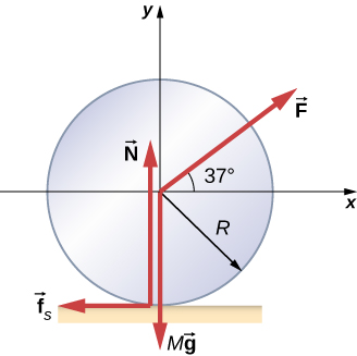
A solid cylindrical wheel of mass M and radius R is pulled by a force [latex]\mathbf{\overset{\to }{F}}[/latex] applied to the center of the wheel at [latex]37^\circ[/latex] to the horizontal (see the following figure). If the wheel is to roll without slipping, what is the maximum value of [latex]|\mathbf{\overset{\to }{F}}|?[/latex] The coefficients of static and kinetic friction are [latex]{\mu }_{\text{S}}=0.40\,\text{and}\,{\mu }_{\text{k}}=0.30.[/latex]
A hollow cylinder is given a velocity of 5.0 m/s and rolls up an incline to a height of 1.0 m. If a hollow sphere of the same mass and radius is given the same initial velocity, how high does it roll up the incline?
Show Solution
Use energy conservation
[latex]\frac{1}{2}m{v}_{0}^{2}+\frac{1}{2}{I}_{\text{Cyl}}{\omega }_{0}^{2}=mg{h}_{\text{Cyl}}[/latex],
[latex]\frac{1}{2}m{v}_{0}^{2}+\frac{1}{2}{I}_{\text{Sph}}{\omega }_{0}^{2}=mg{h}_{\text{Sph}}[/latex].
Subtracting the two equations, eliminating the initial translational energy, we have
[latex]\frac{1}{2}{I}_{\text{Cyl}}{\omega }_{0}^{2}-\frac{1}{2}{I}_{\text{Sph}}{\omega }_{0}^{2}=mg({h}_{\text{Cyl}}-{h}_{\text{Sph}})[/latex],
[latex]\frac{1}{2}m{r}^{2}{(\frac{{v}_{0}}{r})}^{2}-\frac{1}{2}\frac{2}{3}m{r}^{2}{(\frac{{v}_{0}}{r})}^{2}=mg({h}_{\text{Cyl}}-{h}_{\text{Sph}})[/latex],
[latex]\frac{1}{2}{v}_{0}^{2}-\frac{1}{2}\frac{2}{3}{v}_{0}^{2}=g({h}_{\text{Cyl}}-{h}_{\text{Sph}})[/latex],
[latex]{h}_{\text{Cyl}}-{h}_{\text{Sph}}=\frac{1}{g}(\frac{1}{2}-\frac{1}{3}){v}_{0}^{2}=\frac{1}{9.8\,\text{m}\text{/}{\text{s}}^{2}}(\frac{1}{6})(5.0\,\text{m}\text{/}{\text{s)}}^{2}=0.43\,\text{m}[/latex].
Thus, the hollow sphere, with the smaller moment of inertia, rolls up to a lower height of [latex]1.0-0.43=0.57\,\text{m}\text{.}[/latex]
Glossary
- rolling motion
- combination of rotational and translational motion with or without slipping