
12 Static Equilibrium and Elasticity
12.4 Elasticity and Plasticity
Learning Objectives
By the end of this section, you will be able to:
- Explain the limit where a deformation of material is elastic
- Describe the range where materials show plastic behavior
- Analyze elasticity and plasticity on a stress-strain diagram
We referred to the proportionality constant between stress and strain as the elastic modulus. But why do we call it that? What does it mean for an object to be elastic and how do we describe its behavior?
Elasticity is the tendency of solid objects and materials to return to their original shape after the external forces (load) causing a deformation are removed. An object is elastic when it comes back to its original size and shape when the load is no longer present. Physical reasons for elastic behavior vary among materials and depend on the microscopic structure of the material. For example, the elasticity of polymers and rubbers is caused by stretching polymer chains under an applied force. In contrast, the elasticity of metals is caused by resizing and reshaping the crystalline cells of the lattices (which are the material structures of metals) under the action of externally applied forces.
The two parameters that determine the elasticity of a material are its elastic modulus and its elastic limit. A high elastic modulus is typical for materials that are hard to deform; in other words, materials that require a high load to achieve a significant strain. An example is a steel band. A low elastic modulus is typical for materials that are easily deformed under a load; for example, a rubber band. If the stress under a load becomes too high, then when the load is removed, the material no longer comes back to its original shape and size, but relaxes to a different shape and size: The material becomes permanently deformed. The elastic limit is the stress value beyond which the material no longer behaves elastically but becomes permanently deformed.
Our perception of an elastic material depends on both its elastic limit and its elastic modulus. For example, all rubbers are characterized by a low elastic modulus and a high elastic limit; hence, it is easy to stretch them and the stretch is noticeably large. Among materials with identical elastic limits, the most elastic is the one with the lowest elastic modulus.
When the load increases from zero, the resulting stress is in direct proportion to strain in the way given by Figure, but only when stress does not exceed some limiting value. For stress values within this linear limit, we can describe elastic behavior in analogy with Hooke’s law for a spring. According to Hooke’s law, the stretch value of a spring under an applied force is directly proportional to the magnitude of the force. Conversely, the response force from the spring to an applied stretch is directly proportional to the stretch. In the same way, the deformation of a material under a load is directly proportional to the load, and, conversely, the resulting stress is directly proportional to strain. The linearity limit (or the proportionality limit) is the largest stress value beyond which stress is no longer proportional to strain. Beyond the linearity limit, the relation between stress and strain is no longer linear. When stress becomes larger than the linearity limit but still within the elasticity limit, behavior is still elastic, but the relation between stress and strain becomes nonlinear.
For stresses beyond the elastic limit, a material exhibits plastic behavior. This means the material deforms irreversibly and does not return to its original shape and size, even when the load is removed. When stress is gradually increased beyond the elastic limit, the material undergoes plastic deformation. Rubber-like materials show an increase in stress with the increasing strain, which means they become more difficult to stretch and, eventually, they reach a fracture point where they break. Ductile materials such as metals show a gradual decrease in stress with the increasing strain, which means they become easier to deform as stress-strain values approach the breaking point. Microscopic mechanisms responsible for plasticity of materials are different for different materials.
We can graph the relationship between stress and strain on a stress-strain diagram. Each material has its own characteristic strain-stress curve. A typical stress-strain diagram for a ductile metal under a load is shown in Figure. In this figure, strain is a fractional elongation (not drawn to scale). When the load is gradually increased, the linear behavior (red line) that starts at the no-load point (the origin) ends at the linearity limit at point H. For further load increases beyond point H, the stress-strain relation is nonlinear but still elastic. In the figure, this nonlinear region is seen between points H and E. Ever larger loads take the stress to the elasticity limit E, where elastic behavior ends and plastic deformation begins. Beyond the elasticity limit, when the load is removed, for example at P, the material relaxes to a new shape and size along the green line. This is to say that the material becomes permanently deformed and does not come back to its initial shape and size when stress becomes zero.
The material undergoes plastic deformation for loads large enough to cause stress to go beyond the elasticity limit at E. The material continues to be plastically deformed until the stress reaches the fracture point (breaking point). Beyond the fracture point, we no longer have one sample of material, so the diagram ends at the fracture point. For the completeness of this qualitative description, it should be said that the linear, elastic, and plasticity limits denote a range of values rather than one sharp point.
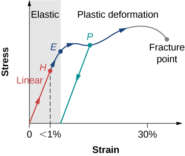
The value of stress at the fracture point is called breaking stress (or ultimate stress). Materials with similar elastic properties, such as two metals, may have very different breaking stresses. For example, ultimate stress for aluminum is [latex]2.2\times {10}^{8}\text{Pa}[/latex] and for steel it may be as high as [latex]20.0\times {10}^{8}\text{Pa},[/latex] depending on the kind of steel. We can make a quick estimate, based on Figure, that for rods with a [latex]{1\text{-in}}^{2}[/latex] cross-sectional area, the breaking load for an aluminum rod is [latex]3.2\times {10}^{4}\,\text{lb},[/latex] and the breaking load for a steel rod is about nine times larger.
Summary
- An object or material is elastic if it comes back to its original shape and size when the stress vanishes. In elastic deformations with stress values lower than the proportionality limit, stress is proportional to strain. When stress goes beyond the proportionality limit, the deformation is still elastic but nonlinear up to the elasticity limit.
- An object or material has plastic behavior when stress is larger than the elastic limit. In the plastic region, the object or material does not come back to its original size or shape when stress vanishes but acquires a permanent deformation. Plastic behavior ends at the breaking point.
Key Equations
| First Equilibrium Condition | [latex]\sum _{k}{\mathbf{\overset{\to }{F}}}_{k}=\mathbf{\overset{\to }{0}}[/latex] |
| Second Equilibrium Condition | [latex]\sum _{k}{\mathbf{\overset{\to }{\tau }}}_{k}\,=\mathbf{\overset{\to }{0}}[/latex] |
| Linear relation between
stress and strain |
[latex]\text{stress}=\text{(elastic modulus)}\times \text{strain}[/latex] |
| Young’s modulus | [latex]Y=\frac{\text{tensile stress}}{\text{tensile strain}}=\frac{{F}_{\perp }}{A}\,\frac{{L}_{0}}{\Delta L}[/latex] |
| Bulk modulus | [latex]B=\frac{\text{bulk stress}}{\text{bulk strain}}=\text{−}\Delta p\frac{{V}_{0}}{\Delta V}[/latex] |
| Shear modulus | [latex]S=\frac{\text{shear stress}}{\text{shear strain}}=\frac{{F}_{\parallel }}{A}\,\frac{{L}_{0}}{\Delta x}[/latex] |
Conceptual Questions
Note: Unless stated otherwise, the weights of the wires, rods, and other elements are assumed to be negligible. Elastic moduli of selected materials are given in Figure.
What is meant when a fishing line is designated as “a 10-lb test?”
Steel rods are commonly placed in concrete before it sets. What is the purpose of these rods?
Show Solution
It acts as “reinforcement,” increasing a range of strain values before the structure reaches its breaking point.
Problems
A uniform rope of cross-sectional area [latex]{0.50\,\text{cm}}^{2}[/latex] breaks when the tensile stress in it reaches [latex]6.00\times {10}^{6}{\text{N/m}}^{2}.[/latex] (a) What is the maximum load that can be lifted slowly at a constant speed by the rope? (b) What is the maximum load that can be lifted by the rope with an acceleration of [latex]{4.00\,\text{m/s}}^{2}\text{?}[/latex]
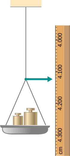
One end of a vertical metallic wire of length 2.0 m and diameter 1.0 mm is attached to a ceiling, and the other end is attached to a 5.0-N weight pan, as shown below. The position of the pointer before the pan is 4.000 cm. Different weights are then added to the pan area, and the position of the pointer is recorded in the table shown. Plot stress versus strain for this wire, then use the resulting curve to determine Young’s modulus and the proportionality limit of the metal. What metal is this most likely to be?
| Added load (including pan)
(N) |
Scale reading
(cm) |
|---|---|
| 0 | 4.000 |
| 15 | 4.036 |
| 25 | 4.073 |
| 35 | 4.109 |
| 45 | 4.146 |
| 55 | 4.181 |
| 65 | 4.221 |
| 75 | 4.266 |
| 85 | 4.316 |
An aluminum [latex](\rho =2.7\,{\text{g/cm}}^{3})[/latex] wire is suspended from the ceiling and hangs vertically. How long must the wire be before the stress at its upper end reaches the proportionality limit, which is [latex]8.0\times {10}^{7}{\text{N/m}}^{2}\text{?}[/latex]
Additional Problems
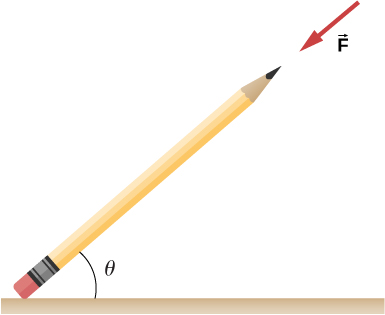
The coefficient of static friction between the rubber eraser of the pencil and the tabletop is [latex]{\mu }_{s}=0.80.[/latex] If the force [latex]\mathbf{\overset{\to }{F}}[/latex] is applied along the axis of the pencil, as shown below, what is the minimum angle at which the pencil can stand without slipping? Ignore the weight of the pencil.
Show Solution
[latex]{\text{tan}}^{-1}(1\text{/}{\mu }_{s})=51.3^\circ[/latex]
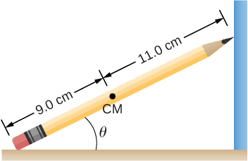
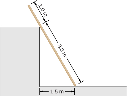
A pencil rests against a corner, as shown below. The sharpened end of the pencil touches a smooth vertical surface and the eraser end touches a rough horizontal floor. The coefficient of static friction between the eraser and the floor is [latex]{\mu }_{s}=0.80.[/latex] The center of mass of the pencil is located 9.0 cm from the tip of the eraser and 11.0 cm from the tip of the pencil lead. Find the minimum angle [latex]\theta[/latex] for which the pencil does not slip.
A uniform 4.0-m plank weighing 200.0 N rests against the corner of a wall, as shown below. There is no friction at the point where the plank meets the corner. (a) Find the forces that the corner and the floor exert on the plank. (b) What is the minimum coefficient of static friction between the floor and the plank to prevent the plank from slipping?
Show Solution
a. at corner 66.7 N at [latex]30^\circ[/latex] with the horizontal; at floor 192.4 N at [latex]60^\circ[/latex] with the horizontal; b. [latex]{\mu }_{\text{s}}=0.577[/latex]
A 40-kg boy jumps from a height of 3.0 m, lands on one foot and comes to rest in 0.10 s after he hits the ground. Assume that he comes to rest with a constant deceleration. If the total cross-sectional area of the bones in his legs just above his ankles is [latex]3.0\,{\text{cm}}^{2},[/latex] what is the compression stress in these bones? Leg bones can be fractured when they are subjected to stress greater than [latex]1.7\times {10}^{8}\,\text{Pa}.[/latex] Is the boy in danger of breaking his leg?
Two thin rods, one made of steel and the other of aluminum, are joined end to end. Each rod is 2.0 m long and has cross-sectional area [latex]9.1\,{\text{mm}}^{2}.[/latex] If a 10,000-N tensile force is applied at each end of the combination, find: (a) stress in each rod; (b) strain in each rod; and, (c) elongation of each rod.
Show Solution
a. [latex]1.10\times {10}^{9}{\text{N/m}}^{2};[/latex] b. [latex]5.5\times {10}^{-3};[/latex] c. 11.0 mm, 31.4 mm
Two rods, one made of copper and the other of steel, have the same dimensions. If the copper rod stretches by 0.15 mm under some stress, how much does the steel rod stretch under the same stress?
Challenge Problems
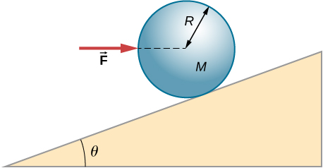
A horizontal force [latex]\mathbf{\overset{\to }{F}}[/latex] is applied to a uniform sphere in direction exact toward the center of the sphere, as shown below. Find the magnitude of this force so that the sphere remains in static equilibrium. What is the frictional force of the incline on the sphere?
Show Solution
[latex]F=\mathit{\text{Mg}}\,\text{tan}\,\theta ;f=0[/latex]
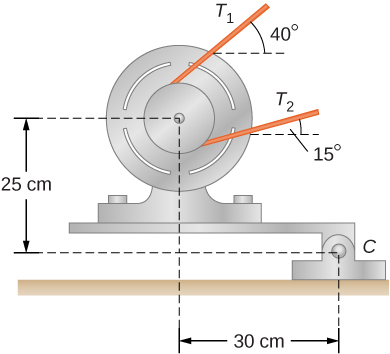
When a motor is set on a pivoted mount seen below, its weight can be used to maintain tension in the drive belt. When the motor is not running the tensions [latex]{T}_{1}[/latex] and [latex]{T}_{2}[/latex] are equal. The total mass of the platform and the motor is 100.0 kg, and the diameter of the drive belt pulley is [latex]16.0\,\text{cm.}[/latex] when the motor is off, find: (a) the tension in the belt, and (b) the force at the hinged platform support at point C. Assume that the center of mass of the motor plus platform is at the center of the motor.
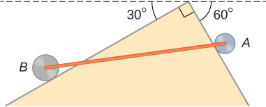
Two wheels A and B with weights w and 2w, respectively, are connected by a uniform rod with weight w/2, as shown below. The wheels are free to roll on the sloped surfaces. Determine the angle that the rod forms with the horizontal when the system is in equilibrium. Hint: There are five forces acting on the rod, which is two weights of the wheels, two normal reaction forces at points where the wheels make contacts with the wedge, and the weight of the rod.
Show Solution
with the horizontal, [latex]\theta =42.2^\circ;[/latex] [latex]\alpha =17.8^\circ[/latex] with the steeper side of the wedge
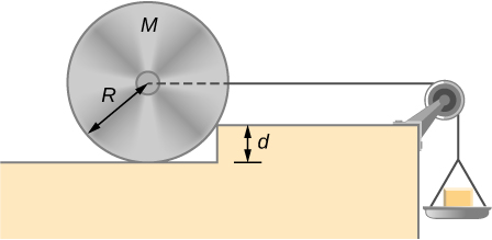
Weights are gradually added to a pan until a wheel of mass M and radius R is pulled over an obstacle of height d, as shown below. What is the minimum mass of the weights plus the pan needed to accomplish this?
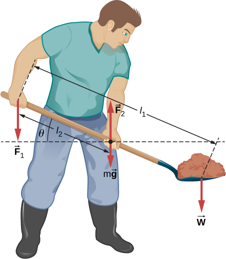
In order to lift a shovelful of dirt, a gardener pushes downward on the end of the shovel and pulls upward at distance [latex]{l}_{2}[/latex] from the end, as shown below. The weight of the shovel is [latex]m\mathbf{\overset{\to }{g}}[/latex] and acts at the point of application of [latex]{\mathbf{\overset{\to }{F}}}_{2}.[/latex] Calculate the magnitudes of the forces [latex]{\mathbf{\overset{\to }{F}}}_{1}[/latex] and [latex]{\mathbf{\overset{\to }{F}}}_{2}[/latex] as functions of [latex]{l}_{1},[/latex] [latex]{l}_{2},[/latex] mg, and the weight W of the load. Why do your answers not depend on the angle [latex]\theta[/latex] that the shovel makes with the horizontal?
Show Solution
[latex]W({l}_{1}\text{/}{l}_{2}-1);W{l}_{1}\text{/}{l}_{2}+mg[/latex]
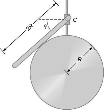
A uniform rod of length 2R and mass M is attached to a small collar C and rests on a cylindrical surface of radius R, as shown below. If the collar can slide without friction along the vertical guide, find the angle [latex]\theta[/latex] for which the rod is in static equilibrium.
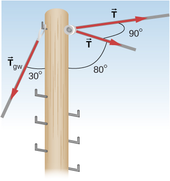
The pole shown below is at a [latex]90.0^\circ[/latex] bend in a power line and is therefore subjected to more shear force than poles in straight parts of the line. The tension in each line is [latex]4.00\times 1{0}^{4}\text{N},[/latex] at the angles shown. The pole is 15.0 m tall, has an 18.0 cm diameter, and can be considered to have half the strength of hardwood. (a) Calculate the compression of the pole. (b) Find how much it bends and in what direction. (c) Find the tension in a guy wire used to keep the pole straight if it is attached to the top of the pole at an angle of [latex]30.0^\circ[/latex] with the vertical. The guy wire is in the opposite direction of the bend.
Show Solution
a. 1.1 mm; b. 6.6 mm to the right; c. [latex]1.11\times {10}^{5}\,\text{N}[/latex]
Glossary
- breaking stress (ultimate stress)
- value of stress at the fracture point
- elastic
- object that comes back to its original size and shape when the load is no longer present
- elastic limit
- stress value beyond which material no longer behaves elastically and becomes permanently deformed
- linearity limit (proportionality limit)
- largest stress value beyond which stress is no longer proportional to strain
- plastic behavior
- material deforms irreversibly, does not go back to its original shape and size when load is removed and stress vanishes
- stress-strain diagram
- graph showing the relationship between stress and strain, characteristic of a material