
10 Fixed-Axis Rotation
10.7 Newton’s Second Law for Rotation
Learning Objectives
By the end of this section, you will be able to:
- Calculate the torques on rotating systems about a fixed axis to find the angular acceleration
- Explain how changes in the moment of inertia of a rotating system affect angular acceleration with a fixed applied torque
In this section, we put together all the pieces learned so far in this chapter to analyze the dynamics of rotating rigid bodies. We have analyzed motion with kinematics and rotational kinetic energy but have not yet connected these ideas with force and/or torque. In this section, we introduce the rotational equivalent to Newton’s second law of motion and apply it to rigid bodies with fixed-axis rotation.
Newton’s Second Law for Rotation
We have thus far found many counterparts to the translational terms used throughout this text, most recently, torque, the rotational analog to force. This raises the question: Is there an analogous equation to Newton’s second law, [latex]\Sigma \mathbf{\overset{\to }{F}}=m\mathbf{\overset{\to }{a}},[/latex] which involves torque and rotational motion? To investigate this, we start with Newton’s second law for a single particle rotating around an axis and executing circular motion. Let’s exert a force [latex]\mathbf{\overset{\to }{F}}[/latex] on a point mass m that is at a distance r from a pivot point (Figure). The particle is constrained to move in a circular path with fixed radius and the force is tangent to the circle. We apply Newton’s second law to determine the magnitude of the acceleration [latex]a=F\text{/}m[/latex] in the direction of [latex]\mathbf{\overset{\to }{F}}[/latex]. Recall that the magnitude of the tangential acceleration is proportional to the magnitude of the angular acceleration by [latex]a=r\alpha[/latex]. Substituting this expression into Newton’s second law, we obtain
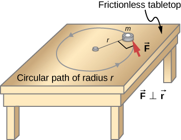
Multiply both sides of this equation by r,
Note that the left side of this equation is the torque about the axis of rotation, where r is the lever arm and F is the force, perpendicular to r. Recall that the moment of inertia for a point particle is[latex]I=m{r}^{2}[/latex]. The torque applied perpendicularly to the point mass in Figure is therefore
The torque on the particle is equal to the moment of inertia about the rotation axis times the angular acceleration. We can generalize this equation to a rigid body rotating about a fixed axis.
Newton’s Second Law for Rotation
If more than one torque acts on a rigid body about a fixed axis, then the sum of the torques equals the moment of inertia times the angular acceleration:
The term [latex]I\alpha[/latex] is a scalar quantity and can be positive or negative (counterclockwise or clockwise) depending upon the sign of the net torque. Remember the convention that counterclockwise angular acceleration is positive. Thus, if a rigid body is rotating clockwise and experiences a positive torque (counterclockwise), the angular acceleration is positive.
Figure is Newton’s second law for rotation and tells us how to relate torque, moment of inertia, and rotational kinematics. This is called the equation for rotational dynamics. With this equation, we can solve a whole class of problems involving force and rotation. It makes sense that the relationship for how much force it takes to rotate a body would include the moment of inertia, since that is the quantity that tells us how easy or hard it is to change the rotational motion of an object.
Deriving Newton’s Second Law for Rotation in Vector Form
As before, when we found the angular acceleration, we may also find the torque vector. The second law [latex]\Sigma \mathbf{\overset{\to }{F}}=m\mathbf{\overset{\to }{a}}[/latex] tells us the relationship between net force and how to change the translational motion of an object. We have a vector rotational equivalent of this equation, which can be found by using Figure and Figure. Figure relates the angular acceleration to the position and tangential acceleration vectors:
We form the cross product of this equation with [latex]\mathbf{\overset{\to }{r}}[/latex] and use a cross product identity (note that [latex]\mathbf{\overset{\to }{r}}\cdot \mathbf{\overset{\to }{\alpha }}=0[/latex]):
We now form the cross product of Newton’s second law with the position vector [latex]\mathbf{\overset{\to }{r}},[/latex]
Identifying the first term on the left as the sum of the torques, and [latex]m{r}^{2}[/latex] as the moment of inertia, we arrive at Newton’s second law of rotation in vector form:
This equation is exactly Figure but with the torque and angular acceleration as vectors. An important point is that the torque vector is in the same direction as the angular acceleration.
Applying the Rotational Dynamics Equation
Before we apply the rotational dynamics equation to some everyday situations, let’s review a general problem-solving strategy for use with this category of problems.
Problem-Solving Strategy: Rotational Dynamics
- Examine the situation to determine that torque and mass are involved in the rotation. Draw a careful sketch of the situation.
- Determine the system of interest.
- Draw a free-body diagram. That is, draw and label all external forces acting on the system of interest.
- Identify the pivot point. If the object is in equilibrium, it must be in equilibrium for all possible pivot points––chose the one that simplifies your work the most.
- Apply [latex]\sum _{i}{\tau }_{i}=I\alpha[/latex], the rotational equivalent of Newton’s second law, to solve the problem. Care must be taken to use the correct moment of inertia and to consider the torque about the point of rotation.
- As always, check the solution to see if it is reasonable.
Example
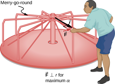
Calculating the Effect of Mass Distribution on a Merry-Go-Round
Consider the father pushing a playground merry-go-round in Figure. He exerts a force of 250 N at the edge of the 50.0-kg merry-go-round, which has a 1.50-m radius. Calculate the angular acceleration produced (a) when no one is on the merry-go-round and (b) when an 18.0-kg child sits 1.25 m away from the center. Consider the merry-go-round itself to be a uniform disk with negligible friction.
Strategy
The net torque is given directly by the expression [latex]\sum _{i}{\tau }_{i}=I\alpha[/latex], To solve for [latex]\alpha[/latex], we must first calculate the net torque [latex]\tau[/latex] (which is the same in both cases) and moment of inertia I (which is greater in the second case).
Solution
- The moment of inertia of a solid disk about this axis is given in Figure to be
[latex]\frac{1}{2}M{R}^{2}.[/latex]
We have [latex]M=50.0\,\text{kg}[/latex] and [latex]R=1.50\,\text{m}[/latex], so
[latex]I=(0.500)(50.0\,\text{kg}){(1.50\,\text{m})}^{2}=56.25{\,\text{kg-m}}^{2}.[/latex]To find the net torque, we note that the applied force is perpendicular to the radius and friction is negligible, so that
[latex]\tau =rF\text{sin}\,\theta =(1.50\,\text{m})(250.0\,\text{N})=375.0\,\text{N-m}.[/latex]Now, after we substitute the known values, we find the angular acceleration to be
[latex]\alpha =\frac{\tau }{I}=\frac{375.0\,\text{N-m}}{56.25{\,\text{kg-m}}^{2}}=6.67\frac{\text{rad}}{{\text{s}}^{2}}.[/latex] - We expect the angular acceleration for the system to be less in this part because the moment of inertia is greater when the child is on the merry-go-round. To find the total moment of inertia I, we first find the child’s moment of inertia [latex]{I}_{\text{c}}[/latex] by approximating the child as a point mass at a distance of 1.25 m from the axis. Then
[latex]{I}_{\text{c}}=m{R}^{2}=(18.0\,\text{kg}){(1.25\,\text{m})}^{2}=28.13{\,\text{kg-m}}^{2}.[/latex]
The total moment of inertia is the sum of the moments of inertia of the merry-go-round and the child (about the same axis):
[latex]I=28.13{\,\text{kg-m}}^{2}+56.25{\,\text{kg-m}}^{2}=84.38{\,\text{kg-m}}^{2}.[/latex]Substituting known values into the equation for α gives
[latex]\alpha =\frac{\tau }{I}=\frac{375.0\,\text{N-m}}{84.38{\,\text{kg-m}}^{2}}=4.44\frac{\text{rad}}{{\text{s}}^{2}}.[/latex]
Significance
The angular acceleration is less when the child is on the merry-go-round than when the merry-go-round is empty, as expected. The angular accelerations found are quite large, partly due to the fact that friction was considered to be negligible. If, for example, the father kept pushing perpendicularly for 2.00 s, he would give the merry-go-round an angular velocity of 13.3 rad/s when it is empty but only 8.89 rad/s when the child is on it. In terms of revolutions per second, these angular velocities are 2.12 rev/s and 1.41 rev/s, respectively. The father would end up running at about 50 km/h in the first case.
Check Your Understanding
The fan blades on a jet engine have a moment of inertia [latex]30.0{\,\text{kg-m}}^{2}[/latex]. In 10 s, they rotate counterclockwise from rest up to a rotation rate of 20 rev/s. (a) What torque must be applied to the blades to achieve this angular acceleration? (b) What is the torque required to bring the fan blades rotating at 20 rev/s to a rest in 20 s?
Show Answer
a. The angular acceleration is [latex]\alpha =\frac{20.0(2\pi )\text{rad}\text{/}\text{s}-0}{10.0\,\text{s}}=12.56\,\text{rad}\text{/}{\text{s}}^{2}[/latex]. Solving for the torque, we have [latex]\sum _{i}{\tau }_{i}=I\alpha =(30.0\,\text{kg}\cdot {\text{m}}^{2})(12.56\,\text{rad}\text{/}{\text{s}}^{2})=376.80\,\text{N}\cdot \text{m}[/latex]; b. The angular acceleration is [latex]\alpha =\frac{0-20.0(2\pi )\text{rad}\text{/}\text{s}}{20.0\,\text{s}}=-6.28\,\text{rad}\text{/}{\text{s}}^{2}[/latex]. Solving for the torque, we have [latex]\sum _{i}{\tau }_{i}=I\alpha =(30.0{\,\text{kg-m}}^{2})(-6.28\,\text{rad}\text{/}{\text{s}}^{2})=-188.50\,\text{N}\cdot \text{m}[/latex]
Summary
- Newton’s second law for rotation, [latex]\sum _{i}{\tau }_{i}=I\alpha[/latex], says that the sum of the torques on a rotating system about a fixed axis equals the product of the moment of inertia and the angular acceleration. This is the rotational analog to Newton’s second law of linear motion.
- In the vector form of Newton’s second law for rotation, the torque vector [latex]\mathbf{\overset{\to }{\tau }}[/latex] is in the same direction as the angular acceleration [latex]\mathbf{\overset{\to }{\alpha }}[/latex]. If the angular acceleration of a rotating system is positive, the torque on the system is also positive, and if the angular acceleration is negative, the torque is negative.
Conceptual Questions
If you were to stop a spinning wheel with a constant force, where on the wheel would you apply the force to produce the maximum negative acceleration?
A rod is pivoted about one end. Two forces [latex]\mathbf{\overset{\to }{F}}\text{and}\,-\mathbf{\overset{\to }{F}}[/latex] are applied to it. Under what circumstances will the rod not rotate?
Show Solution
If the forces are along the axis of rotation, or if they have the same lever arm and are applied at a point on the rod.
Problems
You have a grindstone (a disk) that is 90.0 kg, has a 0.340-m radius, and is turning at 90.0 rpm, and you press a steel axe against it with a radial force of 20.0 N. (a) Assuming the kinetic coefficient of friction between steel and stone is 0.20, calculate the angular acceleration of the grindstone. (b) How many turns will the stone make before coming to rest?
Suppose you exert a force of 180 N tangential to a 0.280-m-radius, 75.0-kg grindstone (a solid disk). (a)What torque is exerted? (b) What is the angular acceleration assuming negligible opposing friction? (c) What is the angular acceleration if there is an opposing frictional force of 20.0 N exerted 1.50 cm from the axis?
Show Solution
a. [latex]\tau =(0.280\,\text{m})(180.0\,\text{N})=50.4\,\text{N}\cdot \text{m}[/latex]; b. [latex]\alpha =17.14\,\text{rad}\text{/}{\text{s}}^{2}[/latex];
c. [latex]\alpha =17.04\,\text{rad}\text{/}{\text{s}}^{2}[/latex]
A flywheel ([latex]I=50{\,\text{kg-m}}^{2}[/latex]) starting from rest acquires an angular velocity of 200.0 rad/s while subject to a constant torque from a motor for 5 s. (a) What is the angular acceleration of the flywheel? (b) What is the magnitude of the torque?
A constant torque is applied to a rigid body whose moment of inertia is [latex]4.0{\,\text{kg-m}}^{2}[/latex] around the axis of rotation. If the wheel starts from rest and attains an angular velocity of 20.0 rad/s in 10.0 s, what is the applied torque?
Show Solution
[latex]\tau =8.0\,\text{N}\cdot \text{m}[/latex]
A torque of 50.0 N-m is applied to a grinding wheel ([latex]I=20.0\,{\text{kg-m}}^{2}[/latex]) for 20 s. (a) If it starts from rest, what is the angular velocity of the grinding wheel after the torque is removed? (b) Through what angle does the wheel move through while the torque is applied?
A flywheel ([latex]I=100.0{\,\text{kg-m}}^{2}[/latex]) rotating at 500.0 rev/min is brought to rest by friction in 2.0 min. What is the frictional torque on the flywheel?
Show Solution
[latex]\tau =-43.6\,\text{N}\cdot \text{m}[/latex]
A uniform cylindrical grinding wheel of mass 50.0 kg and diameter 1.0 m is turned on by an electric motor. The friction in the bearings is negligible. (a) What torque must be applied to the wheel to bring it from rest to 120 rev/min in 20 revolutions? (b) A tool whose coefficient of kinetic friction with the wheel is 0.60 is pressed perpendicularly against the wheel with a force of 40.0 N. What torque must be supplied by the motor to keep the wheel rotating at a constant angular velocity?
Suppose when Earth was created, it was not rotating. However, after the application of a uniform torque after 6 days, it was rotating at 1 rev/day. (a) What was the angular acceleration during the 6 days? (b) What torque was applied to Earth during this period? (c) What force tangent to Earth at its equator would produce this torque?
Show Solution
a. [latex]\alpha =1.4\times {10}^{-10}\,\text{rad}\text{/}{\text{s}}^{2}[/latex];
b. [latex]\tau =1.36\times {10}^{28}\text{N-m}[/latex]; c. [latex]F=2.1\times {10}^{21}\,\text{N}[/latex]
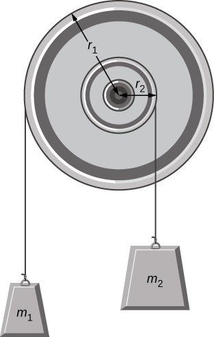
A pulley of moment of inertia [latex]2.0\,{\text{kg-m}}^{2}[/latex] is mounted on a wall as shown in the following figure. Light strings are wrapped around two circumferences of the pulley and weights are attached. What are (a) the angular acceleration of the pulley and (b) the linear acceleration of the weights? Assume the following data: [latex]{r}_{1}=50\,\text{cm},\enspace{r}_{2}=20\,\text{cm},\enspace{m}_{1}=1.0\,\text{kg},\enspace{m}_{2}=2.0\,\text{kg}[/latex].
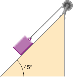
A block of mass 3 kg slides down an inclined plane at an angle of [latex]45^\circ[/latex] with a massless tether attached to a pulley with mass 1 kg and radius 0.5 m at the top of the incline (see the following figure). The pulley can be approximated as a disk. The coefficient of kinetic friction on the plane is 0.4. What is the acceleration of the block?
Show Answer
[latex]a=3.6\,\text{m}\text{/}{\text{s}}^{2}[/latex]
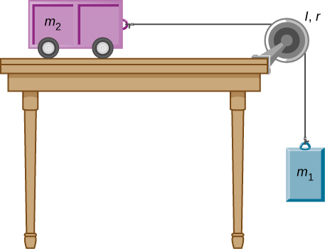
The cart shown below moves across the table top as the block falls. What is the acceleration of the cart? Neglect friction and assume the following data:[latex]{m}_{1}=2.0\,\text{kg},{m}_{2}=4.0\,\text{kg},I=0.4\,{\text{kg-m}}^{2},r=20\,\text{cm}[/latex]
A uniform rod of mass and length is held vertically by two strings of negligible mass, as shown below. (a) Immediately after the string is cut, what is the linear acceleration of the free end of the stick? (b) Of the middle of the stick?
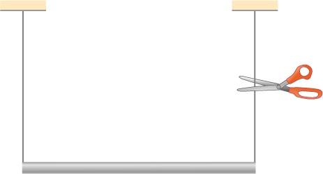
Show Answer
a. [latex]a=r\alpha =14.7\,\text{m}\text{/}{\text{s}}^{2}[/latex]; b. [latex]a=\frac{L}{2}\alpha =\frac{3}{4}g[/latex]
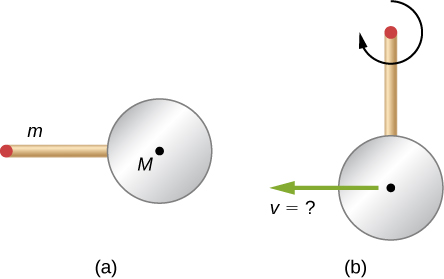
A thin stick of mass 0.2 kg and length [latex]L=0.5\,\text{m}[/latex] is attached to the rim of a metal disk of mass [latex]M=2.0\,\text{kg}[/latex] and radius [latex]R=0.3\,\text{m}[/latex]. The stick is free to rotate around a horizontal axis through its other end (see the following figure). (a) If the combination is released with the stick horizontal, what is the speed of the center of the disk when the stick is vertical? (b) What is the acceleration of the center of the disk at the instant the stick is released? (c) At the instant the stick passes through the vertical?
Glossary
- Newton’s second law for rotation
- sum of the torques on a rotating system equals its moment of inertia times its angular acceleration
- rotational dynamics
- analysis of rotational motion using the net torque and moment of inertia to find the angular acceleration