
6 Applications of Newton’s Laws
6.1 Solving Problems with Newton’s Laws
Learning Objectives
By the end of the section, you will be able to:
- Apply problem-solving techniques to solve for quantities in more complex systems of forces
- Use concepts from kinematics to solve problems using Newton’s laws of motion
- Solve more complex equilibrium problems
- Solve more complex acceleration problems
- Apply calculus to more advanced dynamics problems
Success in problem solving is necessary to understand and apply physical principles. We developed a pattern of analyzing and setting up the solutions to problems involving Newton’s laws in Newton’s Laws of Motion; in this chapter, we continue to discuss these strategies and apply a step-by-step process.
Problem-Solving Strategies
We follow here the basics of problem solving presented earlier in this text, but we emphasize specific strategies that are useful in applying Newton’s laws of motion. Once you identify the physical principles involved in the problem and determine that they include Newton’s laws of motion, you can apply these steps to find a solution. These techniques also reinforce concepts that are useful in many other areas of physics. Many problem-solving strategies are stated outright in the worked examples, so the following techniques should reinforce skills you have already begun to develop.
Problem-Solving Strategy: Applying Newton’s Laws of Motion
- Identify the physical principles involved by listing the givens and the quantities to be calculated.
- Sketch the situation, using arrows to represent all forces.
- Determine the system of interest. The result is a free-body diagram that is essential to solving the problem.
- Apply Newton’s second law to solve the problem. If necessary, apply appropriate kinematic equations from the chapter on motion along a straight line.
- Check the solution to see whether it is reasonable.
Let’s apply this problem-solving strategy to the challenge of lifting a grand piano into a second-story apartment. Once we have determined that Newton’s laws of motion are involved (if the problem involves forces), it is particularly important to draw a careful sketch of the situation. Such a sketch is shown in Figure(a). Then, as in Figure(b), we can represent all forces with arrows. Whenever sufficient information exists, it is best to label these arrows carefully and make the length and direction of each correspond to the represented force.
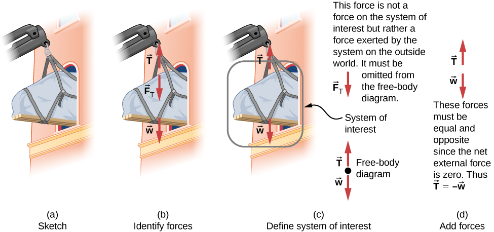
As with most problems, we next need to identify what needs to be determined and what is known or can be inferred from the problem as stated, that is, make a list of knowns and unknowns. It is particularly crucial to identify the system of interest, since Newton’s second law involves only external forces. We can then determine which forces are external and which are internal, a necessary step to employ Newton’s second law. (See Figure(c).) Newton’s third law may be used to identify whether forces are exerted between components of a system (internal) or between the system and something outside (external). As illustrated in Newton’s Laws of Motion, the system of interest depends on the question we need to answer. Only forces are shown in free-body diagrams, not acceleration or velocity. We have drawn several free-body diagrams in previous worked examples. Figure(c) shows a free-body diagram for the system of interest. Note that no internal forces are shown in a free-body diagram.
Once a free-body diagram is drawn, we apply Newton’s second law. This is done in Figure(d) for a particular situation. In general, once external forces are clearly identified in free-body diagrams, it should be a straightforward task to put them into equation form and solve for the unknown, as done in all previous examples. If the problem is one-dimensional—that is, if all forces are parallel—then the forces can be handled algebraically. If the problem is two-dimensional, then it must be broken down into a pair of one-dimensional problems. We do this by projecting the force vectors onto a set of axes chosen for convenience. As seen in previous examples, the choice of axes can simplify the problem. For example, when an incline is involved, a set of axes with one axis parallel to the incline and one perpendicular to it is most convenient. It is almost always convenient to make one axis parallel to the direction of motion, if this is known. Generally, just write Newton’s second law in components along the different directions. Then, you have the following equations:
(If, for example, the system is accelerating horizontally, then you can then set [latex]{a}_{y}=0.[/latex]) We need this information to determine unknown forces acting on a system.
As always, we must check the solution. In some cases, it is easy to tell whether the solution is reasonable. For example, it is reasonable to find that friction causes an object to slide down an incline more slowly than when no friction exists. In practice, intuition develops gradually through problem solving; with experience, it becomes progressively easier to judge whether an answer is reasonable. Another way to check a solution is to check the units. If we are solving for force and end up with units of millimeters per second, then we have made a mistake.
There are many interesting applications of Newton’s laws of motion, a few more of which are presented in this section. These serve also to illustrate some further subtleties of physics and to help build problem-solving skills. We look first at problems involving particle equilibrium, which make use of Newton’s first law, and then consider particle acceleration, which involves Newton’s second law.
Particle Equilibrium
Recall that a particle in equilibrium is one for which the external forces are balanced. Static equilibrium involves objects at rest, and dynamic equilibrium involves objects in motion without acceleration, but it is important to remember that these conditions are relative. For example, an object may be at rest when viewed from our frame of reference, but the same object would appear to be in motion when viewed by someone moving at a constant velocity. We now make use of the knowledge attained in Newton’s Laws of Motion, regarding the different types of forces and the use of free-body diagrams, to solve additional problems in particle equilibrium.
Example
Different Tensions at Different Angles
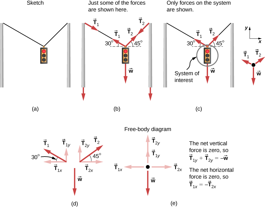
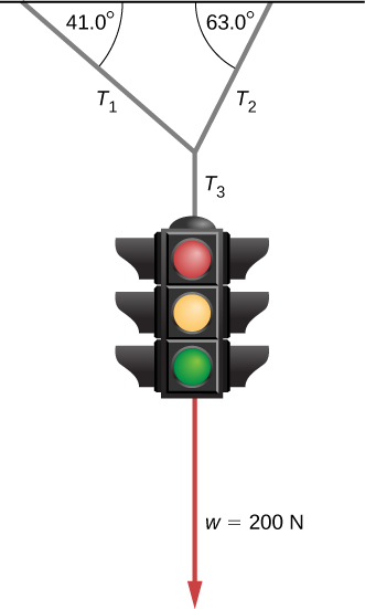
Consider the traffic light (mass of 15.0 kg) suspended from two wires as shown in Figure. Find the tension in each wire, neglecting the masses of the wires.
Strategy
The system of interest is the traffic light, and its free-body diagram is shown in Figure(c). The three forces involved are not parallel, and so they must be projected onto a coordinate system. The most convenient coordinate system has one axis vertical and one horizontal, and the vector projections on it are shown in Figure(d). There are two unknowns in this problem ([latex]{T}_{1}[/latex] and [latex]{T}_{2}[/latex]), so two equations are needed to find them. These two equations come from applying Newton’s second law along the vertical and horizontal axes, noting that the net external force is zero along each axis because acceleration is zero.
Solution
First consider the horizontal or x-axis:
Thus, as you might expect,
This gives us the following relationship:
Thus,
Note that [latex]{T}_{1}[/latex] and [latex]{T}_{2}[/latex] are not equal in this case because the angles on either side are not equal. It is reasonable that [latex]{T}_{2}[/latex] ends up being greater than [latex]{T}_{1}[/latex] because it is exerted more vertically than [latex]{T}_{1}.[/latex]
Now consider the force components along the vertical or y-axis:
This implies
Substituting the expressions for the vertical components gives
There are two unknowns in this equation, but substituting the expression for [latex]{T}_{2}[/latex] in terms of [latex]{T}_{1}[/latex] reduces this to one equation with one unknown:
which yields
Solving this last equation gives the magnitude of [latex]{T}_{1}[/latex] to be
Finally, we find the magnitude of [latex]{T}_{2}[/latex] by using the relationship between them, [latex]{T}_{2}=1.225{T}_{1}[/latex], found above. Thus we obtain
Significance
Both tensions would be larger if both wires were more horizontal, and they will be equal if and only if the angles on either side are the same (as they were in the earlier example of a tightrope walker in Newton’s Laws of Motion.
Particle Acceleration
We have given a variety of examples of particles in equilibrium. We now turn our attention to particle acceleration problems, which are the result of a nonzero net force. Refer again to the steps given at the beginning of this section, and notice how they are applied to the following examples.
Example
Drag Force on a Barge
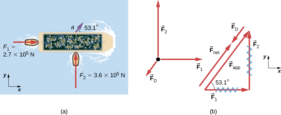
Two tugboats push on a barge at different angles (Figure). The first tugboat exerts a force of [latex]2.7\times {10}^{5}\,\text{N}[/latex] in the x-direction, and the second tugboat exerts a force of [latex]3.6\times {10}^{5}\,\text{N}[/latex] in the y-direction. The mass of the barge is [latex]5.0\times {10}^{6}\,\text{kg}[/latex] and its acceleration is observed to be [latex]7.5\times {10}^{-2}\,{\text{m/s}}^{2}[/latex] in the direction shown. What is the drag force of the water on the barge resisting the motion? (Note: Drag force is a frictional force exerted by fluids, such as air or water. The drag force opposes the motion of the object. Since the barge is flat bottomed, we can assume that the drag force is in the direction opposite of motion of the barge.)
Strategy
The directions and magnitudes of acceleration and the applied forces are given in Figure(a). We define the total force of the tugboats on the barge as [latex]{\mathbf{\overset{\to }{F}}}_{\text{app}}[/latex] so that
The drag of the water [latex]{\mathbf{\overset{\to }{F}}}_{\text{D}}[/latex] is in the direction opposite to the direction of motion of the boat; this force thus works against [latex]{\mathbf{\overset{\to }{F}}}_{\text{app}},[/latex] as shown in the free-body diagram in Figure(b). The system of interest here is the barge, since the forces on it are given as well as its acceleration. Because the applied forces are perpendicular, the x– and y-axes are in the same direction as [latex]{\mathbf{\overset{\to }{F}}}_{1}[/latex] and [latex]{\mathbf{\overset{\to }{F}}}_{2}.[/latex] The problem quickly becomes a one-dimensional problem along the direction of [latex]{\mathbf{\overset{\to }{F}}}_{\text{app}}[/latex], since friction is in the direction opposite to [latex]{\mathbf{\overset{\to }{F}}}_{\text{app}}.[/latex] Our strategy is to find the magnitude and direction of the net applied force [latex]{\mathbf{\overset{\to }{F}}}_{\text{app}}[/latex] and then apply Newton’s second law to solve for the drag force [latex]{\mathbf{\overset{\to }{F}}}_{\text{D}}.[/latex]
Solution
Since [latex]{F}_{x}[/latex] and [latex]{F}_{y}[/latex] are perpendicular, we can find the magnitude and direction of [latex]{\mathbf{\overset{\to }{F}}}_{\text{app}}[/latex] directly. First, the resultant magnitude is given by the Pythagorean theorem:
The angle is given by
From Newton’s first law, we know this is the same direction as the acceleration. We also know that [latex]{\mathbf{\overset{\to }{F}}}_{\text{D}}[/latex] is in the opposite direction of [latex]{\mathbf{\overset{\to }{F}}}_{\text{app}},[/latex] since it acts to slow down the acceleration. Therefore, the net external force is in the same direction as [latex]{\mathbf{\overset{\to }{F}}}_{\text{app}},[/latex] but its magnitude is slightly less than [latex]{\mathbf{\overset{\to }{F}}}_{\text{app}}.[/latex] The problem is now one-dimensional. From the free-body diagram, we can see that
However, Newton’s second law states that
Thus,
This can be solved for the magnitude of the drag force of the water [latex]{F}_{\text{D}}[/latex] in terms of known quantities:
Substituting known values gives
The direction of [latex]{\mathbf{\overset{\to }{F}}}_{\text{D}}[/latex] has already been determined to be in the direction opposite to [latex]{\mathbf{\overset{\to }{F}}}_{\text{app}},[/latex] or at an angle of [latex]53^\circ[/latex] south of west.
Significance
The numbers used in this example are reasonable for a moderately large barge. It is certainly difficult to obtain larger accelerations with tugboats, and small speeds are desirable to avoid running the barge into the docks. Drag is relatively small for a well-designed hull at low speeds, consistent with the answer to this example, where [latex]{F}_{\text{D}}[/latex] is less than 1/600th of the weight of the ship.
In Newton’s Laws of Motion, we discussed the normal force, which is a contact force that acts normal to the surface so that an object does not have an acceleration perpendicular to the surface. The bathroom scale is an excellent example of a normal force acting on a body. It provides a quantitative reading of how much it must push upward to support the weight of an object. But can you predict what you would see on the dial of a bathroom scale if you stood on it during an elevator ride? Will you see a value greater than your weight when the elevator starts up? What about when the elevator moves upward at a constant speed? Take a guess before reading the next example.
Example
What Does the Bathroom Scale Read in an Elevator?
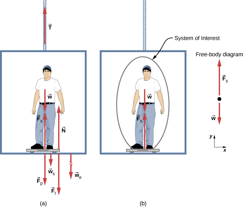
Figure shows a 75.0-kg man (weight of about 165 lb.) standing on a bathroom scale in an elevator. Calculate the scale reading: (a) if the elevator accelerates upward at a rate of [latex]1.20\,{\text{m/s}}^{2},[/latex] and (b) if the elevator moves upward at a constant speed of 1 m/s.
Strategy
If the scale at rest is accurate, its reading equals [latex]{\mathbf{\overset{\to }{F}}}_{\text{p}}[/latex], the magnitude of the force the person exerts downward on it. Figure(a) shows the numerous forces acting on the elevator, scale, and person. It makes this one-dimensional problem look much more formidable than if the person is chosen to be the system of interest and a free-body diagram is drawn, as in Figure(b). Analysis of the free-body diagram using Newton’s laws can produce answers to both Figure(a) and (b) of this example, as well as some other questions that might arise. The only forces acting on the person are his weight [latex]\mathbf{\overset{\to }{w}}[/latex] and the upward force of the scale [latex]{\mathbf{\overset{\to }{F}}}_{\text{s}}.[/latex] According to Newton’s third law, [latex]{\mathbf{\overset{\to }{F}}}_{\text{p}}[/latex] and [latex]{\mathbf{\overset{\to }{F}}}_{\text{s}}[/latex] are equal in magnitude and opposite in direction, so that we need to find [latex]{F}_{\text{s}}[/latex] in order to find what the scale reads. We can do this, as usual, by applying Newton’s second law,
From the free-body diagram, we see that [latex]{\mathbf{\overset{\to }{F}}}_{\text{net}}={\mathbf{\overset{\to }{F}}}_{s}-\mathbf{\overset{\to }{w}},[/latex] so we have
Solving for [latex]{F}_{s}[/latex] gives us an equation with only one unknown:
or, because [latex]w=mg,[/latex] simply
No assumptions were made about the acceleration, so this solution should be valid for a variety of accelerations in addition to those in this situation. (Note: We are considering the case when the elevator is accelerating upward. If the elevator is accelerating downward, Newton’s second law becomes [latex]{F}_{s}-w=\text{−}ma.[/latex])
Solution
- We have [latex]a=1.20\,{\text{m/s}}^{2},[/latex] so that
[latex]{F}_{\text{s}}=(75.0\,\text{kg})(9.80\,{\text{m/s}}^{2})+(75.0\,\text{kg})(1.20\,{\text{m/s}}^{2})[/latex]
yielding
[latex]{F}_{\text{s}}=825\,\text{N}\text{.}[/latex] - Now, what happens when the elevator reaches a constant upward velocity? Will the scale still read more than his weight? For any constant velocity—up, down, or stationary—acceleration is zero because [latex]a=\frac{\Delta v}{\Delta t}[/latex] and [latex]\Delta v=0.[/latex] Thus,
[latex]{F}_{\text{s}}=ma+mg=0+mg[/latex]
or
[latex]{F}_{\text{s}}=(75.0\,\text{kg})(9.80\,{\text{m/s}}^{2}),[/latex]which gives
[latex]{F}_{\text{s}}=735\,\text{N}\text{.}[/latex]
Significance
The scale reading in Figure(a) is about 185 lb. What would the scale have read if he were stationary? Since his acceleration would be zero, the force of the scale would be equal to his weight:
Thus, the scale reading in the elevator is greater than his 735-N (165-lb.) weight. This means that the scale is pushing up on the person with a force greater than his weight, as it must in order to accelerate him upward. Clearly, the greater the acceleration of the elevator, the greater the scale reading, consistent with what you feel in rapidly accelerating versus slowly accelerating elevators. In Figure(b), the scale reading is 735 N, which equals the person’s weight. This is the case whenever the elevator has a constant velocity—moving up, moving down, or stationary.
Check Your Understanding
Now calculate the scale reading when the elevator accelerates downward at a rate of [latex]1.20\,{\text{m/s}}^{2}.[/latex]
Show Solution
[latex]{F}_{\text{s}}=645\,\text{N}[/latex]
The solution to the previous example also applies to an elevator accelerating downward, as mentioned. When an elevator accelerates downward, a is negative, and the scale reading is less than the weight of the person. If a constant downward velocity is reached, the scale reading again becomes equal to the person’s weight. If the elevator is in free fall and accelerating downward at g, then the scale reading is zero and the person appears to be weightless.
Example
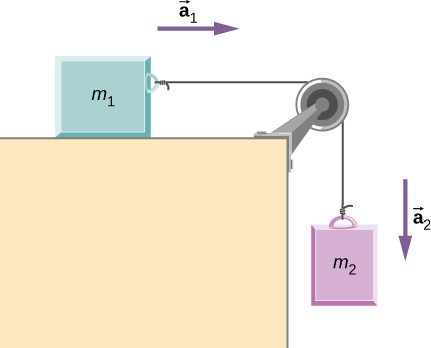
Two Attached Blocks
Figure shows a block of mass [latex]{m}_{1}[/latex] on a frictionless, horizontal surface. It is pulled by a light string that passes over a frictionless and massless pulley. The other end of the string is connected to a block of mass [latex]{m}_{2}.[/latex] Find the acceleration of the blocks and the tension in the string in terms of [latex]{m}_{1},{m}_{2},\,\text{and}\,g.[/latex]
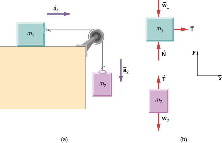
Strategy
We draw a free-body diagram for each mass separately, as shown in Figure. Then we analyze each one to find the required unknowns. The forces on block 1 are the gravitational force, the contact force of the surface, and the tension in the string. Block 2 is subjected to the gravitational force and the string tension. Newton’s second law applies to each, so we write two vector equations:
For block 1: [latex]\mathbf{\overset{\to }{T}}+{\mathbf{\overset{\to }{w}}}_{1}+\mathbf{\overset{\to }{N}}={m}_{1}{\mathbf{\overset{\to }{a}}}_{1}[/latex]
For block 2: [latex]\mathbf{\overset{\to }{T}}+{\mathbf{\overset{\to }{w}}}_{2}={m}_{2}{\mathbf{\overset{\to }{a}}}_{2}.[/latex]
Notice that [latex]\mathbf{\overset{\to }{T}}[/latex] is the same for both blocks. Since the string and the pulley have negligible mass, and since there is no friction in the pulley, the tension is the same throughout the string. We can now write component equations for each block. All forces are either horizontal or vertical, so we can use the same horizontal/vertical coordinate system for both objects
Solution
The component equations follow from the vector equations above. We see that block 1 has the vertical forces balanced, so we ignore them and write an equation relating the x-components. There are no horizontal forces on block 2, so only the y-equation is written. We obtain these results:
When block 1 moves to the right, block 2 travels an equal distance downward; thus, [latex]{a}_{1x}=\text{−}{a}_{2y}.[/latex] Writing the common acceleration of the blocks as [latex]a={a}_{1x}=\text{−}{a}_{2y},[/latex] we now have
and
From these two equations, we can express a and T in terms of the masses [latex]{m}_{1}\,\text{and}\,{m}_{2},\,\text{and}\,g:[/latex]
and
Significance
Notice that the tension in the string is less than the weight of the block hanging from the end of it. A common error in problems like this is to set [latex]T={m}_{2}g.[/latex] You can see from the free-body diagram of block 2 that cannot be correct if the block is accelerating.
Check Your Understanding
Calculate the acceleration of the system, and the tension in the string, when the masses are [latex]{m}_{1}=5.00\,\text{kg}[/latex] and [latex]{m}_{2}=3.00\,\text{kg}.[/latex]
Show Solution
[latex]a=3.68\,{\text{m/s}}^{2},[/latex] [latex]T=18.4\,\text{N}[/latex]
Example
Atwood Machine
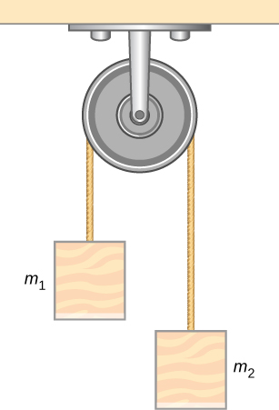
A classic problem in physics, similar to the one we just solved, is that of the Atwood machine, which consists of a rope running over a pulley, with two objects of different mass attached. It is particularly useful in understanding the connection between force and motion. In Figure, [latex]{m}_{1}=2.00\,\text{kg}[/latex] and [latex]{m}_{2}=4.00\,\text{kg}\text{.}[/latex] Consider the pulley to be frictionless. (a) If [latex]{m}_{2}[/latex] is released, what will its acceleration be? (b) What is the tension in the string?
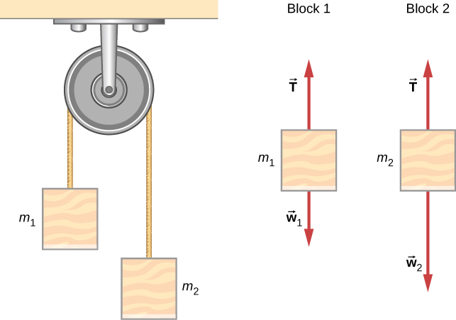
Strategy
We draw a free-body diagram for each mass separately, as shown in the figure. Then we analyze each diagram to find the required unknowns. This may involve the solution of simultaneous equations. It is also important to note the similarity with the previous example. As block 2 accelerates with acceleration [latex]{a}_{2}[/latex] in the downward direction, block 1 accelerates upward with acceleration [latex]{a}_{1}[/latex]. Thus, [latex]a={a}_{1}=\text{−}{a}_{2}.[/latex]
Solution
- We have
[latex]\begin{array}{c}\text{For}\,{m}_{1},\,\sum {F}_{y}=T-{m}_{1}g={m}_{1}a.\hfill \\ \text{For}\,{m}_{2},\,\sum {F}_{y}=T-{m}_{2}g=\text{−}{m}_{2}a.\hfill \end{array}[/latex]
(The negative sign in front of [latex]{m}_{2}a[/latex] indicates that [latex]{m}_{2}[/latex] accelerates downward; both blocks accelerate at the same rate, but in opposite directions.) Solve the two equations simultaneously (subtract them) and the result is
[latex]({m}_{2}-{m}_{1})g=({m}_{1}+{m}_{2})a.[/latex]Solving for a:
[latex]a=\frac{{m}_{2}-{m}_{1}}{{m}_{1}+{m}_{2}}g=\frac{4\,\text{kg}-2\,\text{kg}}{4\,\text{kg}+2\,\text{kg}}(9.8\,{\text{m/s}}^{2})=3.27\,{\text{m/s}}^{2}.[/latex] - Observing the first block, we see that
[latex]\begin{array}{c}T-{m}_{1}g={m}_{1}a\hfill \\ T={m}_{1}(g+a)=(2\,\text{kg})(9.8\,{\text{m/s}}^{2}+3.27\,{\text{m/s}}^{2})=26.1\,\text{N}\text{.}\hfill \end{array}[/latex]
Significance
The result for the acceleration given in the solution can be interpreted as the ratio of the unbalanced force on the system, [latex]({m}_{2}-{m}_{1})g[/latex], to the total mass of the system, [latex]{m}_{1}+{m}_{2}[/latex]. We can also use the Atwood machine to measure local gravitational field strength.
Check Your Understanding
Determine a general formula in terms of [latex]{m}_{1},{m}_{2}[/latex] and g for calculating the tension in the string for the Atwood machine shown above.
Newton’s Laws of Motion and Kinematics
Physics is most interesting and most powerful when applied to general situations that involve more than a narrow set of physical principles. Newton’s laws of motion can also be integrated with other concepts that have been discussed previously in this text to solve problems of motion. For example, forces produce accelerations, a topic of kinematics, and hence the relevance of earlier chapters.
When approaching problems that involve various types of forces, acceleration, velocity, and/or position, listing the givens and the quantities to be calculated will allow you to identify the principles involved. Then, you can refer to the chapters that deal with a particular topic and solve the problem using strategies outlined in the text. The following worked example illustrates how the problem-solving strategy given earlier in this chapter, as well as strategies presented in other chapters, is applied to an integrated concept problem.
Example
What Force Must a Soccer Player Exert to Reach Top Speed?
A soccer player starts at rest and accelerates forward, reaching a velocity of 8.00 m/s in 2.50 s. (a) What is her average acceleration? (b) What average force does the ground exert forward on the runner so that she achieves this acceleration? The player’s mass is 70.0 kg, and air resistance is negligible.
Strategy
To find the answers to this problem, we use the problem-solving strategy given earlier in this chapter. The solutions to each part of the example illustrate how to apply specific problem-solving steps. In this case, we do not need to use all of the steps. We simply identify the physical principles, and thus the knowns and unknowns; apply Newton’s second law; and check to see whether the answer is reasonable.
Solution
- We are given the initial and final velocities (zero and 8.00 m/s forward); thus, the change in velocity is [latex]\Delta v=8.00\,\text{m/s}[/latex]. We are given the elapsed time, so [latex]\Delta t=2.50\,\text{s}\text{.}[/latex] The unknown is acceleration, which can be found from its definition:
[latex]a=\frac{\Delta v}{\Delta t}.[/latex]
Substituting the known values yields
[latex]a=\frac{8.00\,\text{m/s}}{2.50\,\text{s}}=3.20\,{\text{m/s}}^{2}.[/latex] - Here we are asked to find the average force the ground exerts on the runner to produce this acceleration. (Remember that we are dealing with the force or forces acting on the object of interest.) This is the reaction force to that exerted by the player backward against the ground, by Newton’s third law. Neglecting air resistance, this would be equal in magnitude to the net external force on the player, since this force causes her acceleration. Since we now know the player’s acceleration and are given her mass, we can use Newton’s second law to find the force exerted. That is,
[latex]{F}_{\text{net}}=ma.[/latex]
Substituting the known values of m and a gives
[latex]{F}_{\text{net}}=(70.0\,\text{kg})(3.20\,{\text{m/s}}^{2})=224\,\text{N}\text{.}[/latex]
This is a reasonable result: The acceleration is attainable for an athlete in good condition. The force is about 50 pounds, a reasonable average force.
Significance
This example illustrates how to apply problem-solving strategies to situations that include topics from different chapters. The first step is to identify the physical principles, the knowns, and the unknowns involved in the problem. The second step is to solve for the unknown, in this case using Newton’s second law. Finally, we check our answer to ensure it is reasonable. These techniques for integrated concept problems will be useful in applications of physics outside of a physics course, such as in your profession, in other science disciplines, and in everyday life.
Check Your Understanding
The soccer player stops after completing the play described above, but now notices that the ball is in position to be stolen. If she now experiences a force of 126 N to attempt to steal the ball, which is 2.00 m away from her, how long will it take her to get to the ball?
Show Solution
1.49 s
Example
What Force Acts on a Model Helicopter?
A 1.50-kg model helicopter has a velocity of [latex]5.00\mathbf{\hat{j}}\,\text{m/s}[/latex] at [latex]t=0.[/latex] It is accelerated at a constant rate for two seconds (2.00 s) after which it has a velocity of [latex](6.00\mathbf{\hat{i}}+12.00\mathbf{\hat{j}})\text{m/s}\text{.}[/latex] What is the magnitude of the resultant force acting on the helicopter during this time interval?
Strategy
We can easily set up a coordinate system in which the x-axis [latex](\mathbf{\hat{i}}[/latex] direction) is horizontal, and the y-axis [latex](\mathbf{\hat{j}}[/latex] direction) is vertical. We know that [latex]\Delta t=2.00s[/latex] and [latex](6.00\mathbf{\hat{i}}+12.00\mathbf{\hat{j}}\,\text{m/s})-(5.00\mathbf{\hat{j}}\,\text{m/s}).[/latex] From this, we can calculate the acceleration by the definition; we can then apply Newton’s second law.
Solution
We have
The magnitude of the force is now easily found:
Significance
The original problem was stated in terms of [latex]\mathbf{\hat{i}}-\mathbf{\hat{j}}[/latex] vector components, so we used vector methods. Compare this example with the previous example.
Check Your Understanding
Find the direction of the resultant for the 1.50-kg model helicopter.
Show Solution
49.4 degrees
Example
Baggage Tractor
Figure(a) shows a baggage tractor pulling luggage carts from an airplane. The tractor has mass 650.0 kg, while cart A has mass 250.0 kg and cart B has mass 150.0 kg. The driving force acting for a brief period of time accelerates the system from rest and acts for 3.00 s. (a) If this driving force is given by [latex]F=(820.0t)\,\text{N,}[/latex] find the speed after 3.00 seconds. (b) What is the horizontal force acting on the connecting cable between the tractor and cart A at this instant?
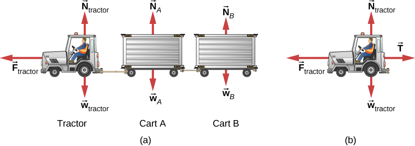
Strategy
A free-body diagram shows the driving force of the tractor, which gives the system its acceleration. We only need to consider motion in the horizontal direction. The vertical forces balance each other and it is not necessary to consider them. For part b, we make use of a free-body diagram of the tractor alone to determine the force between it and cart A. This exposes the coupling force [latex]\mathbf{\overset{\to }{T}},[/latex] which is our objective.
Solution
- [latex]\sum {F}_{x}={m}_{\text{system}}{a}_{x}[/latex] and [latex]\sum {F}_{x}=820.0t,[/latex] so
[latex]\begin{array}{ccc}\hfill 820.0t& =\hfill & (650.0+250.0+150.0)a\hfill \\ \hfill a& =\hfill & 0.7809t.\hfill \end{array}[/latex]
Since acceleration is a function of time, we can determine the velocity of the tractor by using [latex]a=\frac{dv}{dt}[/latex] with the initial condition that [latex]{v}_{0}=0[/latex] at [latex]t=0.[/latex] We integrate from [latex]t=0[/latex] to [latex]t=3\text{:}[/latex]
[latex]dv=adt,\enspace{\int }_{0}^{3}dv={\int }_{0}^{3.00}adt={\int }_{0}^{3.00}0.7809tdt,\enspace v=0.3905{{t}^{2}]}_{0}^{3.00}=3.51\,\text{m/s}\text{.}[/latex] - Refer to the free-body diagram in Figure(b).
[latex]\begin{array}{ccc}\hfill \sum {F}_{x}& =\hfill & {m}_{\text{tractor}}{a}_{x}\hfill \\ \hfill 820.0t-T& =\hfill & {m}_{\text{tractor}}(0.7805)t\hfill \\ \hfill (820.0)(3.00)-T& =\hfill & (650.0)(0.7805)(3.00)\hfill \\ \hfill T& =\hfill & 938\,\text{N}.\hfill \end{array}[/latex]
Significance
Since the force varies with time, we must use calculus to solve this problem. Notice how the total mass of the system was important in solving Figure(a), whereas only the mass of the truck (since it supplied the force) was of use in Figure(b).
Recall that [latex]v=\frac{ds}{dt}[/latex] and [latex]a=\frac{dv}{dt}[/latex]. If acceleration is a function of time, we can use the calculus forms developed in Motion Along a Straight Line, as shown in this example. However, sometimes acceleration is a function of displacement. In this case, we can derive an important result from these calculus relations. Solving for dt in each, we have [latex]dt=\frac{ds}{v}[/latex] and [latex]dt=\frac{dv}{a}.[/latex] Now, equating these expressions, we have [latex]\frac{ds}{v}=\frac{dv}{a}.[/latex] We can rearrange this to obtain [latex]{a}^{}ds={v}^{}dv.[/latex]
Example
Motion of a Projectile Fired Vertically
A 10.0-kg mortar shell is fired vertically upward from the ground, with an initial velocity of 50.0 m/s (see Figure). Determine the maximum height it will travel if atmospheric resistance is measured as [latex]{F}_{\text{D}}=(0.0100{v}^{2})\,\text{N,}[/latex] where v is the speed at any instant.
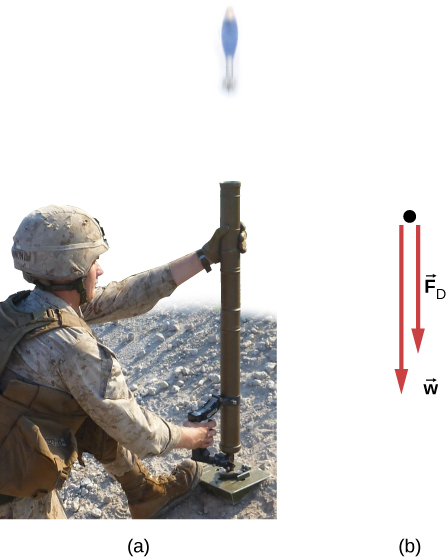
Strategy
The known force on the mortar shell can be related to its acceleration using the equations of motion. Kinematics can then be used to relate the mortar shell’s acceleration to its position.
Solution
Initially, [latex]{y}_{0}=0[/latex] and [latex]{v}_{0}=50.0\,\text{m/s}\text{.}[/latex] At the maximum height [latex]y=h,v=0.[/latex] The free-body diagram shows [latex]{F}_{\text{D}}[/latex] to act downward, because it slows the upward motion of the mortar shell. Thus, we can write
The acceleration depends on v and is therefore variable. Since [latex]a=f(v)\text{,}[/latex] we can relate a to v using the rearrangement described above,
We replace ds with dy because we are dealing with the vertical direction,
We now separate the variables (v’s and dv’s on one side; dy on the other):
Thus, [latex]h=114\,\text{m}\text{.}[/latex]
Significance
Notice the need to apply calculus since the force is not constant, which also means that acceleration is not constant. To make matters worse, the force depends on v (not t), and so we must use the trick explained prior to the example. The answer for the height indicates a lower elevation if there were air resistance. We will deal with the effects of air resistance and other drag forces in greater detail in Drag Force and Terminal Speed.
Check Your Understanding
If atmospheric resistance is neglected, find the maximum height for the mortar shell. Is calculus required for this solution?
Show Solution
128 m; no
Explore the forces at work in this simulation when you try to push a filing cabinet. Create an applied force and see the resulting frictional force and total force acting on the cabinet. Charts show the forces, position, velocity, and acceleration vs. time. View a free-body diagram of all the forces (including gravitational and normal forces).
Summary
- Newton’s laws of motion can be applied in numerous situations to solve motion problems.
- Some problems contain multiple force vectors acting in different directions on an object. Be sure to draw diagrams, resolve all force vectors into horizontal and vertical components, and draw a free-body diagram. Always analyze the direction in which an object accelerates so that you can determine whether [latex]{F}_{\text{net}}=ma[/latex] or [latex]{F}_{\text{net}}=0.[/latex]
- The normal force on an object is not always equal in magnitude to the weight of the object. If an object is accelerating vertically, the normal force is less than or greater than the weight of the object. Also, if the object is on an inclined plane, the normal force is always less than the full weight of the object.
- Some problems contain several physical quantities, such as forces, acceleration, velocity, or position. You can apply concepts from kinematics and dynamics to solve these problems.
Conceptual Questions
To simulate the apparent weightlessness of space orbit, astronauts are trained in the hold of a cargo aircraft that is accelerating downward at g. Why do they appear to be weightless, as measured by standing on a bathroom scale, in this accelerated frame of reference? Is there any difference between their apparent weightlessness in orbit and in the aircraft?
Show Solution
The scale is in free fall along with the astronauts, so the reading on the scale would be 0. There is no difference in the apparent weightlessness; in the aircraft and in orbit, free fall is occurring.
Problems
A 30.0-kg girl in a swing is pushed to one side and held at rest by a horizontal force [latex]\mathbf{\overset{\to }{F}}[/latex] so that the swing ropes are [latex]30.0^\circ[/latex] with respect to the vertical. (a) Calculate the tension in each of the two ropes supporting the swing under these conditions. (b) Calculate the magnitude of [latex]\mathbf{\overset{\to }{F}}.[/latex]
Show Solution
a. 170 N; b. 170 N
Find the tension in each of the three cables supporting the traffic light if it weighs 2.00 × 10² N.
Three forces act on an object, considered to be a particle, which moves with constant velocity [latex]v=(3\mathbf{\hat{i}}-2\mathbf{\hat{j}})\,\text{m/s}\text{.}[/latex] Two of the forces are [latex]{\mathbf{\overset{\to }{F}}}_{1}=(3\mathbf{\hat{i}}+5\mathbf{\hat{j}}-6\mathbf{\hat{k}})\,\text{N}[/latex] and [latex]{\mathbf{\overset{\to }{F}}}_{2}=(4\mathbf{\hat{i}}-7\mathbf{\hat{j}}+2\mathbf{\hat{k}})\,\text{N}\text{.}[/latex] Find the third force.
Show Solution
[latex]{\mathbf{\overset{\to }{F}}}_{3}=(-7\mathbf{\hat{i}}+2\mathbf{\hat{j}}+4\mathbf{\hat{k}})\,\text{N}[/latex]
A flea jumps by exerting a force of [latex]1.20\times {10}^{-5}\,\text{N}[/latex] straight down on the ground. A breeze blowing on the flea parallel to the ground exerts a force of [latex]0.500\times {10}^{-6}\,\text{N}[/latex] on the flea while the flea is still in contact with the ground. Find the direction and magnitude of the acceleration of the flea if its mass is [latex]6.00\times {10}^{-7}\,\text{kg}[/latex]. Do not neglect the gravitational force.
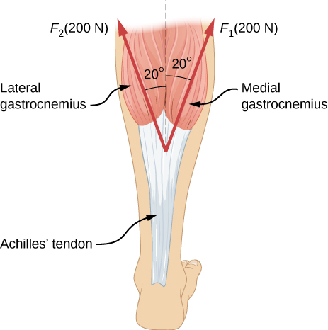
Two muscles in the back of the leg pull upward on the Achilles tendon, as shown below. (These muscles are called the medial and lateral heads of the gastrocnemius muscle.) Find the magnitude and direction of the total force on the Achilles tendon. What type of movement could be caused by this force?
Show Solution
376 N pointing up (along the dashed line in the figure); the force is used to raise the heel of the foot.
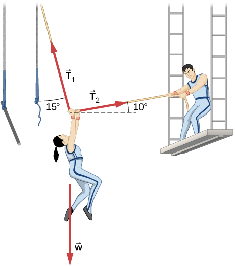
After a mishap, a 76.0-kg circus performer clings to a trapeze, which is being pulled to the side by another circus artist, as shown here. Calculate the tension in the two ropes if the person is momentarily motionless. Include a free-body diagram in your solution.
A 35.0-kg dolphin decelerates from 12.0 to 7.50 m/s in 2.30 s to join another dolphin in play. What average force was exerted to slow the first dolphin if it was moving horizontally? (The gravitational force is balanced by the buoyant force of the water.)
Show Solution
−68.5 N
When starting a foot race, a 70.0-kg sprinter exerts an average force of 650 N backward on the ground for 0.800 s. (a) What is his final speed? (b) How far does he travel?
A large rocket has a mass of [latex]2.00\times {10}^{6}\,\text{kg}[/latex] at takeoff, and its engines produce a thrust of [latex]3.50\times {10}^{7}\,\text{N}.[/latex] (a) Find its initial acceleration if it takes off vertically. (b) How long does it take to reach a velocity of 120 km/h straight up, assuming constant mass and thrust?
Show Solution
a. [latex]7.70\,{\text{m/s}}^{2}[/latex]; b. 4.33 s
A basketball player jumps straight up for a ball. To do this, he lowers his body 0.300 m and then accelerates through this distance by forcefully straightening his legs. This player leaves the floor with a vertical velocity sufficient to carry him 0.900 m above the floor. (a) Calculate his velocity when he leaves the floor. (b) Calculate his acceleration while he is straightening his legs. He goes from zero to the velocity found in (a) in a distance of 0.300 m. (c) Calculate the force he exerts on the floor to do this, given that his mass is 110.0 kg.
A 2.50-kg fireworks shell is fired straight up from a mortar and reaches a height of 110.0 m. (a) Neglecting air resistance (a poor assumption, but we will make it for this example), calculate the shell’s velocity when it leaves the mortar. (b) The mortar itself is a tube 0.450 m long. Calculate the average acceleration of the shell in the tube as it goes from zero to the velocity found in (a). (c) What is the average force on the shell in the mortar? Express your answer in newtons and as a ratio to the weight of the shell.
Show Solution
a. 46.4 m/s; b. [latex]2.40\times {10}^{3}\,{\text{m/s}}^{2}\text{;}[/latex] c. 5.99 × 10³ N; ratio of 245
A 0.500-kg potato is fired at an angle of [latex]80.0^\circ[/latex] above the horizontal from a PVC pipe used as a “potato gun” and reaches a height of 110.0 m. (a) Neglecting air resistance, calculate the potato’s velocity when it leaves the gun. (b) The gun itself is a tube 0.450 m long. Calculate the average acceleration of the potato in the tube as it goes from zero to the velocity found in (a). (c) What is the average force on the potato in the gun? Express your answer in newtons and as a ratio to the weight of the potato.
An elevator filled with passengers has a mass of [latex]1.70\times {10}^{3}\,\text{kg}[/latex]. (a) The elevator accelerates upward from rest at a rate of [latex]1.20\,{\text{m/s}}^{2}[/latex] for 1.50 s. Calculate the tension in the cable supporting the elevator. (b) The elevator continues upward at constant velocity for 8.50 s. What is the tension in the cable during this time? (c) The elevator decelerates at a rate of [latex]0.600\,{\text{m/s}}^{2}[/latex] for 3.00 s. What is the tension in the cable during deceleration? (d) How high has the elevator moved above its original starting point, and what is its final velocity?
Show Solution
a. [latex]1.87\times {10}^{4}\,\text{N;}[/latex] b. [latex]1.67\times {10}^{4}\,\text{N;}[/latex] c. [latex]1.56\times {10}^{4}\,\text{N;}[/latex] d. 19.4 m, 0 m/s
A 20.0-g ball hangs from the roof of a freight car by a string. When the freight car begins to move, the string makes an angle of [latex]35.0^\circ[/latex] with the vertical. (a) What is the acceleration of the freight car? (b) What is the tension in the string?
A student’s backpack, full of textbooks, is hung from a spring scale attached to the ceiling of an elevator. When the elevator is accelerating downward at [latex]3.8\,{\text{m/s}}^{2}[/latex], the scale reads 60 N. (a) What is the mass of the backpack? (b) What does the scale read if the elevator moves upward while slowing down at a rate [latex]3.8\,{\text{m/s}}^{2}[/latex]? (c) What does the scale read if the elevator moves upward at constant velocity? (d) If the elevator had no brakes and the cable supporting it were to break loose so that the elevator could fall freely, what would the spring scale read?
Show Solution
a. 10 kg; b. 90 N; c. 98 N; d. 0
A service elevator takes a load of garbage, mass 10.0 kg, from a floor of a skyscraper under construction, down to ground level, accelerating downward at a rate of [latex]1.2\,{\text{m/s}}^{2}[/latex]. Find the magnitude of the force the garbage exerts on the floor of the service elevator?
A roller coaster car starts from rest at the top of a track 30.0 m long and inclined at [latex]20.0^\circ[/latex] to the horizontal. Assume that friction can be ignored. (a) What is the acceleration of the car? (b) How much time elapses before it reaches the bottom of the track?
Show Solution
a. [latex]3.35\,{\text{m/s}}^{2}[/latex]; b. 4.2 s
The device shown below is the Atwood’s machine considered in Figure. Assuming that the masses of the string and the frictionless pulley are negligible, (a) find an equation for the acceleration of the two blocks; (b) find an equation for the tension in the string; and (c) find both the acceleration and tension when block 1 has mass 2.00 kg and block 2 has mass 4.00 kg.
Two blocks are connected by a massless rope as shown below. The mass of the block on the table is 4.0 kg and the hanging mass is 1.0 kg. The table and the pulley are frictionless. (a) Find the acceleration of the system. (b) Find the tension in the rope. (c) Find the speed with which the hanging mass hits the floor if it starts from rest and is initially located 1.0 m from the floor.
Show Solution
a. [latex]2.0\,{\text{m/s}}^{2};[/latex] b. 7.8 N; c. 2.0 m/s
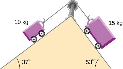
Shown below are two carts connected by a cord that passes over a small frictionless pulley. Each cart rolls freely with negligible friction. Calculate the acceleration of the carts and the tension in the cord.
A 2.00 kg block (mass 1) and a 4.00 kg block (mass 2) are connected by a light string as shown; the inclination of the ramp is [latex]40.0^\circ[/latex]. Friction is negligible. What is (a) the acceleration of each block and (b) the tension in the string?
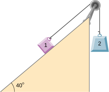
a. [latex]0.933\,{\text{m/s}}^{2}[/latex] (mass 1 accelerates up the ramp as mass 2 falls with the same acceleration); b. 21.5 NShow Solution