
5 Newton’s Laws of Motion
5.7 Drawing Free-Body Diagrams
Learning Objectives
By the end of the section, you will be able to:
- Explain the rules for drawing a free-body diagram
- Construct free-body diagrams for different situations
The first step in describing and analyzing most phenomena in physics involves the careful drawing of a free-body diagram. Free-body diagrams have been used in examples throughout this chapter. Remember that a free-body diagram must only include the external forces acting on the body of interest. Once we have drawn an accurate free-body diagram, we can apply Newton’s first law if the body is in equilibrium (balanced forces; that is, [latex]{F}_{\text{net}}=0[/latex]) or Newton’s second law if the body is accelerating (unbalanced force; that is, [latex]{F}_{\text{net}}\ne 0[/latex]).
In Forces, we gave a brief problem-solving strategy to help you understand free-body diagrams. Here, we add some details to the strategy that will help you in constructing these diagrams.
Problem-Solving Strategy: Constructing Free-Body Diagrams
Observe the following rules when constructing a free-body diagram:
- Draw the object under consideration; it does not have to be artistic. At first, you may want to draw a circle around the object of interest to be sure you focus on labeling the forces acting on the object. If you are treating the object as a particle (no size or shape and no rotation), represent the object as a point. We often place this point at the origin of an xy-coordinate system.
- Include all forces that act on the object, representing these forces as vectors. Consider the types of forces described in Common Forces—normal force, friction, tension, and spring force—as well as weight and applied force. Do not include the net force on the object. With the exception of gravity, all of the forces we have discussed require direct contact with the object. However, forces that the object exerts on its environment must not be included. We never include both forces of an action-reaction pair.
- Convert the free-body diagram into a more detailed diagram showing the x– and y-components of a given force (this is often helpful when solving a problem using Newton’s first or second law). In this case, place a squiggly line through the original vector to show that it is no longer in play—it has been replaced by its x– and y-components.
- If there are two or more objects, or bodies, in the problem, draw a separate free-body diagram for each object.
Note: If there is acceleration, we do not directly include it in the free-body diagram; however, it may help to indicate acceleration outside the free-body diagram. You can label it in a different color to indicate that it is separate from the free-body diagram.
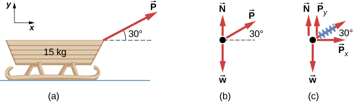
Let’s apply the problem-solving strategy in drawing a free-body diagram for a sled. In Figure(a), a sled is pulled by force P at an angle of [latex]30^\circ[/latex]. In part (b), we show a free-body diagram for this situation, as described by steps 1 and 2 of the problem-solving strategy. In part (c), we show all forces in terms of their x– and y-components, in keeping with step 3.
Example
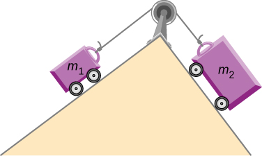
Two Blocks on an Inclined Plane
Construct the free-body diagram for object A and object B in Figure.
Strategy
We follow the four steps listed in the problem-solving strategy.
Solution
We start by creating a diagram for the first object of interest. In Figure(a), object A is isolated (circled) and represented by a dot.
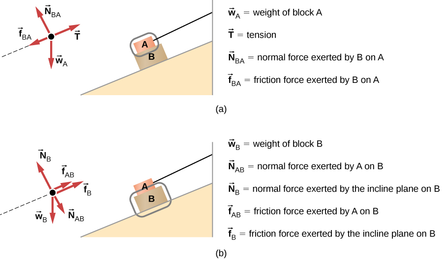
We now include any force that acts on the body. Here, no applied force is present. The weight of the object acts as a force pointing vertically downward, and the presence of the cord indicates a force of tension pointing away from the object. Object A has one interface and hence experiences a normal force, directed away from the interface. The source of this force is object B, and this normal force is labeled accordingly. Since object B has a tendency to slide down, object A has a tendency to slide up with respect to the interface, so the friction [latex]{f}_{\text{BA}}[/latex] is directed downward parallel to the inclined plane.
As noted in step 4 of the problem-solving strategy, we then construct the free-body diagram in Figure(b) using the same approach. Object B experiences two normal forces and two friction forces due to the presence of two contact surfaces. The interface with the inclined plane exerts external forces of [latex]{N}_{\text{B}}[/latex] and [latex]{f}_{\text{B}}[/latex], and the interface with object B exerts the normal force [latex]{N}_{\text{AB}}[/latex] and friction [latex]{f}_{\text{AB}}[/latex]; [latex]{N}_{\text{AB}}[/latex] is directed away from object B, and [latex]{f}_{\text{AB}}[/latex] is opposing the tendency of the relative motion of object B with respect to object A.
Significance
The object under consideration in each part of this problem was circled in gray. When you are first learning how to draw free-body diagrams, you will find it helpful to circle the object before deciding what forces are acting on that particular object. This focuses your attention, preventing you from considering forces that are not acting on the body.
Example
Two Blocks in Contact
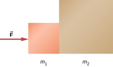
A force is applied to two blocks in contact, as shown.
Strategy
Draw a free-body diagram for each block. Be sure to consider Newton’s third law at the interface where the two blocks touch.
Solution
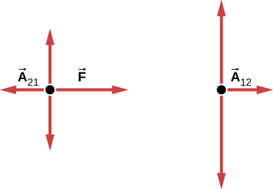
Significance[latex]{\mathbf{\overset{\to }{A}}}_{21}[/latex] is the action force of block 2 on block 1. [latex]{\mathbf{\overset{\to }{A}}}_{12}[/latex] is the reaction force of block 1 on block 2. We use these free-body diagrams in Applications of Newton’s Laws.
Example
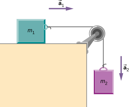
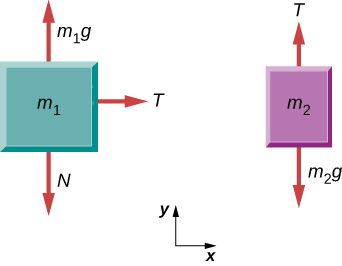
Block on the Table (Coupled Blocks)
A block rests on the table, as shown. A light rope is attached to it and runs over a pulley. The other end of the rope is attached to a second block. The two blocks are said to be coupled. Block [latex]{m}_{2}[/latex] exerts a force due to its weight, which causes the system (two blocks and a string) to accelerate.
Strategy
We assume that the string has no mass so that we do not have to consider it as a separate object. Draw a free-body diagram for each block.
Solution
Significance
Each block accelerates (notice the labels shown for [latex]{\mathbf{\overset{\to }{a}}}_{1}[/latex] and [latex]{\mathbf{\overset{\to }{a}}}_{2}[/latex]); however, assuming the string remains taut, they accelerate at the same rate. Thus, we have [latex]{\mathbf{\overset{\to }{a}}}_{1}={\mathbf{\overset{\to }{a}}}_{2}[/latex]. If we were to continue solving the problem, we could simply call the acceleration [latex]\mathbf{\overset{\to }{a}}[/latex]. Also, we use two free-body diagrams because we are usually finding tension T, which may require us to use a system of two equations in this type of problem. The tension is the same on both [latex]{m}_{1}\,\text{and}\,{m}_{2}[/latex].
Check Your Understanding
(a) Draw the free-body diagram for the situation shown. (b) Redraw it showing components; use x-axes parallel to the two ramps.
Show Solution
Figure a shows a free body diagram of an object on a line that slopes down to the right. Arrow T from the object points right and up, parallel to the slope. Arrow N1 points left and up, perpendicular to the slope. Arrow w1 points vertically down. Arrow w1x points left and down, parallel to the slope. Arrow w1y points right and down, perpendicular to the slope. Figure b shows a free body diagram of an object on a line that slopes down to the left. Arrow N2 from the object points right and up, perpendicular to the slope. Arrow T points left and up, parallel to the slope. Arrow w2 points vertically down. Arrow w2y points left and down, perpendicular to the slope. Arrow w2x points right and down, parallel to the slope.
View this simulation to predict, qualitatively, how an external force will affect the speed and direction of an object’s motion. Explain the effects with the help of a free-body diagram. Use free-body diagrams to draw position, velocity, acceleration, and force graphs, and vice versa. Explain how the graphs relate to one another. Given a scenario or a graph, sketch all four graphs.
Summary
- To draw a free-body diagram, we draw the object of interest, draw all forces acting on that object, and resolve all force vectors into x– and y-components. We must draw a separate free-body diagram for each object in the problem.
- A free-body diagram is a useful means of describing and analyzing all the forces that act on a body to determine equilibrium according to Newton’s first law or acceleration according to Newton’s second law.
Key Equations
| Net external force | [latex]{\mathbf{\overset{\to }{F}}}_{\text{net}}=\sum \mathbf{\overset{\to }{F}}={\mathbf{\overset{\to }{F}}}_{1}+{\mathbf{\overset{\to }{F}}}_{2}+\cdots[/latex] |
| Newton’s first law | [latex]\mathbf{\overset{\to }{v}}=\,\text{constant when}\,{\mathbf{\overset{\to }{F}}}_{\text{net}}=\mathbf{\overset{\to }{0}}\,\text{N}[/latex] |
| Newton’s second law, vector form | [latex]{\mathbf{\overset{\to }{F}}}_{\text{net}}=\sum \mathbf{\overset{\to }{F}}=m\mathbf{\overset{\to }{a}}[/latex] |
| Newton’s second law, scalar form | [latex]{F}_{\text{net}}=ma[/latex] |
| Newton’s second law, component form | [latex]\sum {\mathbf{\overset{\to }{F}}}_{x}=m{\mathbf{\overset{\to }{a}}}_{x}\text{,}\,\sum {\mathbf{\overset{\to }{F}}}_{y}=m{\mathbf{\overset{\to }{a}}}_{y},\,\text{and}\,\sum {\mathbf{\overset{\to }{F}}}_{z}=m{\mathbf{\overset{\to }{a}}}_{z}.[/latex] |
| Newton’s second law, momentum form | [latex]{\mathbf{\overset{\to }{F}}}_{\text{net}}=\frac{d\mathbf{\overset{\to }{p}}}{dt}[/latex] |
| Definition of weight, vector form | [latex]\mathbf{\overset{\to }{w}}=m\mathbf{\overset{\to }{g}}[/latex] |
| Definition of weight, scalar form | [latex]w=mg[/latex] |
| Newton’s third law | [latex]{\mathbf{\overset{\to }{F}}}_{\text{AB}}=\text{−}{\mathbf{\overset{\to }{F}}}_{\text{BA}}[/latex] |
| Normal force on an object resting on a
horizontal surface, vector form |
[latex]\mathbf{\overset{\to }{N}}=\text{−}m\mathbf{\overset{\to }{g}}[/latex] |
| Normal force on an object resting on a
horizontal surface, scalar form |
[latex]N=mg[/latex] |
| Normal force on an object resting on an
inclined plane, scalar form |
[latex]N=mg\text{cos}\,\theta[/latex] |
| Tension in a cable supporting an object
of mass m at rest, scalar form |
[latex]T=w=mg[/latex] |
Conceptual Questions
In completing the solution for a problem involving forces, what do we do after constructing the free-body diagram? That is, what do we apply?
If a book is located on a table, how many forces should be shown in a free-body diagram of the book? Describe them.
Show Solution
Two forces of different types: weight acting downward and normal force acting upward
Problems
A ball of mass m hangs at rest, suspended by a string. (a) Sketch all forces. (b) Draw the free-body diagram for the ball.
A car moves along a horizontal road. Draw a free-body diagram; be sure to include the friction of the road that opposes the forward motion of the car.
Show Solution
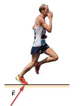
A runner pushes against the track, as shown. (a) Provide a free-body diagram showing all the forces on the runner. (Hint: Place all forces at the center of his body, and include his weight.) (b) Give a revised diagram showing the xy-component form.
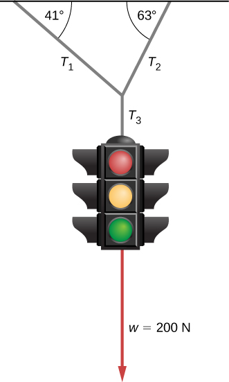
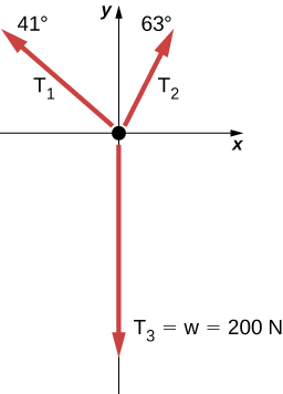
The traffic light hangs from the cables as shown. Draw a free-body diagram on a coordinate plane for this situation.
Show Solution
Additional Problems
Two small forces, [latex]{\mathbf{\overset{\to }{F}}}_{1}=-2.40\mathbf{\hat{i}}-6.10t\mathbf{\hat{j}}[/latex] N and [latex]{\mathbf{\overset{\to }{F}}}_{2}=8.50\mathbf{\hat{i}}-9.70\mathbf{\hat{j}}[/latex] N, are exerted on a rogue asteroid by a pair of space tractors. (a) Find the net force. (b) What are the magnitude and direction of the net force? (c) If the mass of the asteroid is 125 kg, what acceleration does it experience (in vector form)? (d) What are the magnitude and direction of the acceleration?
Two forces of 25 and 45 N act on an object. Their directions differ by [latex]70^\circ[/latex]. The resulting acceleration has magnitude of [latex]10.0\,{\text{m/s}}^{2}.[/latex] What is the mass of the body?
Show Solution
5.90 kg
A force of 1600 N acts parallel to a ramp to push a 300-kg piano into a moving van. The ramp is inclined at [latex]20^\circ[/latex]. (a) What is the acceleration of the piano up the ramp? (b) What is the velocity of the piano when it reaches the top if the ramp is 4.0 m long and the piano starts from rest?
Draw a free-body diagram of a diver who has entered the water, moved downward, and is acted on by an upward force due to the water which balances the weight (that is, the diver is suspended).
Show Solution

For a swimmer who has just jumped off a diving board, assume air resistance is negligible. The swimmer has a mass of 80.0 kg and jumps off a board 10.0 m above the water. Three seconds after entering the water, her downward motion is stopped. What average upward force did the water exert on her?
(a) Find an equation to determine the magnitude of the net force required to stop a car of mass m, given that the initial speed of the car is [latex]{v}_{0}[/latex] and the stopping distance is x. (b) Find the magnitude of the net force if the mass of the car is 1050 kg, the initial speed is 40.0 km/h, and the stopping distance is 25.0 m.
Show Solution
a. [latex]{F}_{\text{net}}=\frac{m({v}^{2}-{v}_{0}{}^{2})}{2x}[/latex]; b. 2590 N
A sailboat has a mass of [latex]1.50\times {10}^{3}[/latex] kg and is acted on by a force of [latex]2.00\times {10}^{3}[/latex] N toward the east, while the wind acts behind the sails with a force of [latex]3.00\times {10}^{3}[/latex] N in a direction [latex]45^\circ[/latex] north of east. Find the magnitude and direction of the resulting acceleration.
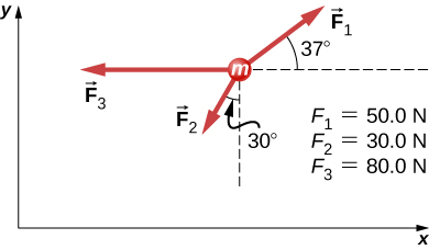
Find the acceleration of the body of mass 10.0 kg shown below.
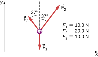
Show Answer
[latex]\begin{array}{cc} {\mathbf{\overset{\to }{F}}}_{\text{net}}=4.05\mathbf{\hat{i}}+12.0\mathbf{\hat{j}}\text{N}\hfill \\ {\mathbf{\overset{\to }{F}}}_{\text{net}}=m\mathbf{\overset{\to }{a}}\Rightarrow \mathbf{\overset{\to }{a}}=0.405\mathbf{\hat{i}}+1.20\mathbf{\hat{j}}\,{\text{m/s}}^{2}\hfill \end{array}[/latex]
A body of mass 2.0 kg is moving along the x-axis with a speed of 3.0 m/s at the instant represented below. (a) What is the acceleration of the body? (b) What is the body’s velocity 10.0 s later? (c) What is its displacement after 10.0 s?
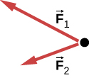
Force [latex]{\mathbf{\overset{\to }{F}}}_{\text{B}}[/latex] has twice the magnitude of force [latex]{\mathbf{\overset{\to }{F}}}_{\text{A}}.[/latex] Find the direction in which the particle accelerates in this figure.
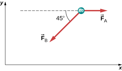
Show Answer
[latex]\begin{array}{cc} {\mathbf{\overset{\to }{F}}}_{\text{net}}={\mathbf{\overset{\to }{F}}}_{\text{A}}+{\mathbf{\overset{\to }{F}}}_{\text{B}}\hfill \\ {\mathbf{\overset{\to }{F}}}_{\text{net}}=A\mathbf{\hat{i}}+(-1.41A\mathbf{\hat{i}}-1.41A\mathbf{\hat{j}})\hfill \\ {\mathbf{\overset{\to }{F}}}_{\text{net}}=A(-0.41\mathbf{\hat{i}}-1.41\mathbf{\hat{j}})\hfill \\ \theta =254^\circ\hfill \end{array}[/latex]
(We add [latex]180^\circ[/latex], because the angle is in quadrant IV.)
Shown below is a body of mass 1.0 kg under the influence of the forces [latex]{\mathbf{\overset{\to }{F}}}_{A}[/latex], [latex]{\mathbf{\overset{\to }{F}}}_{B}[/latex], and [latex]m\mathbf{\overset{\to }{g}}[/latex]. If the body accelerates to the left at [latex]20\,{\text{m/s}}^{2}[/latex], what are [latex]{\mathbf{\overset{\to }{F}}}_{A}[/latex] and [latex]{\mathbf{\overset{\to }{F}}}_{B}[/latex]?
A force acts on a car of mass m so that the speed v of the car increases with position x as [latex]v=k{x}^{2}[/latex], where k is constant and all quantities are in SI units. Find the force acting on the car as a function of position.
Show Solution
[latex]F=2kmx[/latex]; First, take the derivative of the velocity function to obtain [latex]a=2kx[/latex]. Then apply Newton’s second law [latex]F=ma=m(2kx)=2kmx[/latex].
A 7.0-N force parallel to an incline is applied to a 1.0-kg crate. The ramp is tilted at [latex]20^\circ[/latex] and is frictionless. (a) What is the acceleration of the crate? (b) If all other conditions are the same but the ramp has a friction force of 1.9 N, what is the acceleration?
Two boxes, A and B, are at rest. Box A is on level ground, while box B rests on an inclined plane tilted at angle [latex]\theta[/latex] with the horizontal. (a) Write expressions for the normal force acting on each block. (b) Compare the two forces; that is, tell which one is larger or whether they are equal in magnitude. (c) If the angle of incline is [latex]10^\circ[/latex], which force is greater?
Show Solution
a. For box A, [latex]{N}_{\text{A}}=mg[/latex] and [latex]{N}_{\text{B}}=mg\,\text{cos}\,\theta[/latex]; b. [latex]{N}_{\text{A}} \gt {N}_{\text{B}}[/latex] because for [latex]\theta \lt 90^\circ[/latex], [latex]\text{cos}\,\theta \lt 1[/latex]; c. [latex]{N}_{\text{A}} \gt {N}_{\text{B}}[/latex] when [latex]\theta =10^\circ[/latex]
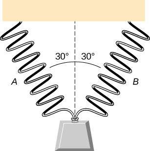
As shown below, two identical springs, each with the spring constant 20 N/m, support a 15.0-N weight. (a) What is the tension in spring A? (b) What is the amount of stretch of spring A from the rest position?
Show Solution
a. 8.66 N; b. 0.433 m
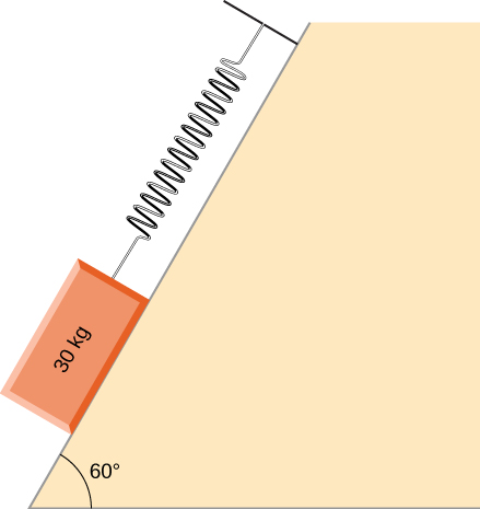
Shown below is a 30.0-kg block resting on a frictionless ramp inclined at [latex]60^\circ[/latex] to the horizontal. The block is held by a spring that is stretched 5.0 cm. What is the force constant of the spring?
In building a house, carpenters use nails from a large box. The box is suspended from a spring twice during the day to measure the usage of nails. At the beginning of the day, the spring stretches 50 cm. At the end of the day, the spring stretches 30 cm. What fraction or percentage of the nails have been used?
Show Solution
0.40 or 40%
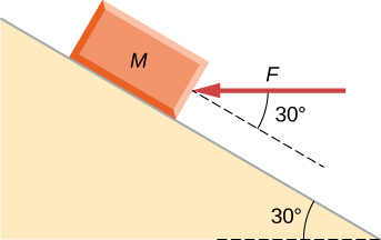
A force is applied to a block to move it up a [latex]30^\circ[/latex] incline. The incline is frictionless. If [latex]F=65.0\,\text{N}[/latex] and [latex]M=5.00\,\text{kg}[/latex], what is the magnitude of the acceleration of the block?
Two forces are applied to a 5.0-kg object, and it accelerates at a rate of [latex]2.0\,{\text{m/s}}^{2}[/latex] in the positive y-direction. If one of the forces acts in the positive x-direction with magnitude 12.0 N, find the magnitude of the other force.
Show Solution
16 N
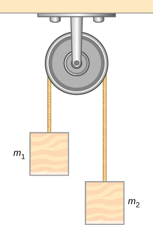
The block on the right shown below has more mass than the block on the left ([latex]{m}_{2} \gt {m}_{1}[/latex]). Draw free-body diagrams for each block.
Challenge Problems
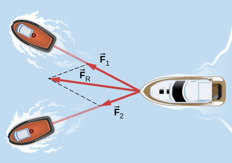
If two tugboats pull on a disabled vessel, as shown here in an overhead view, the disabled vessel will be pulled along the direction indicated by the result of the exerted forces. (a) Draw a free-body diagram for the vessel. Assume no friction or drag forces affect the vessel. (b) Did you include all forces in the overhead view in your free-body diagram? Why or why not?
Show Solution
a.
b. No; [latex]{\mathbf{\overset{\to }{F}}}_{\text{R}}[/latex] is not shown, because it would replace [latex]{\mathbf{\overset{\to }{F}}}_{1}[/latex] and [latex]{\mathbf{\overset{\to }{F}}}_{2}[/latex]. (If we want to show it, we could draw it and then place squiggly lines on [latex]{\mathbf{\overset{\to }{F}}}_{1}[/latex] and [latex]{\mathbf{\overset{\to }{F}}}_{2}[/latex] to show that they are no longer considered.
A 10.0-kg object is initially moving east at 15.0 m/s. Then a force acts on it for 2.00 s, after which it moves northwest, also at 15.0 m/s. What are the magnitude and direction of the average force that acted on the object over the 2.00-s interval?
On June 25, 1983, shot-putter Udo Beyer of East Germany threw the 7.26-kg shot 22.22 m, which at that time was a world record. (a) If the shot was released at a height of 2.20 m with a projection angle of [latex]45.0^\circ[/latex], what was its initial velocity? (b) If while in Beyer’s hand the shot was accelerated uniformly over a distance of 1.20 m, what was the net force on it?
Show Solution
a. 14.1 m/s; b. 601 N
A body of mass m moves in a horizontal direction such that at time t its position is given by [latex]x(t)=a{t}^{4}+b{t}^{3}+ct,[/latex] where a, b, and c are constants. (a) What is the acceleration of the body? (b) What is the time-dependent force acting on the body?
A body of mass m has initial velocity [latex]{v}_{0}[/latex] in the positive x-direction. It is acted on by a constant force F for time t until the velocity becomes zero; the force continues to act on the body until its velocity becomes [latex]\text{−}{v}_{0}[/latex] in the same amount of time. Write an expression for the total distance the body travels in terms of the variables indicated.
Show Solution
[latex]\frac{F}{m}{t}^{2}[/latex]
The velocities of a 3.0-kg object at [latex]t=6.0\,\text{s}[/latex] and [latex]t=8.0\,\text{s}[/latex] are [latex](3.0\mathbf{\hat{i}}-6.0\mathbf{\hat{j}}+4.0\mathbf{\hat{k}})\,\text{m/s}[/latex] and [latex](-2.0\mathbf{\hat{i}}+4.0\mathbf{\hat{k}})\,\text{m/s}[/latex], respectively. If the object is moving at constant acceleration, what is the force acting on it?
A 120-kg astronaut is riding in a rocket sled that is sliding along an inclined plane. The sled has a horizontal component of acceleration of [latex]5.0\,\text{m}\text{/}{\text{s}}^{2}[/latex] and a downward component of [latex]3.8\,\text{m}\text{/}{\text{s}}^{2}[/latex]. Calculate the magnitude of the force on the rider by the sled. (Hint: Remember that gravitational acceleration must be considered.)
Show Solution
936 N
Two forces are acting on a 5.0-kg object that moves with acceleration [latex]2.0\,{\text{m/s}}^{2}[/latex] in the positive y-direction. If one of the forces acts in the positive x-direction and has magnitude of 12 N, what is the magnitude of the other force?
Suppose that you are viewing a soccer game from a helicopter above the playing field. Two soccer players simultaneously kick a stationary soccer ball on the flat field; the soccer ball has mass 0.420 kg. The first player kicks with force 162 N at [latex]9.0^\circ[/latex] north of west. At the same instant, the second player kicks with force 215 N at [latex]15^\circ[/latex] east of south. Find the acceleration of the ball in [latex]\mathbf{\hat{i}}[/latex] and [latex]\mathbf{\hat{j}}[/latex] form.
Show Solution
[latex]\mathbf{\overset{\to }{a}}=-248\mathbf{\hat{i}}-433\mathbf{\hat{j}}\text{m}\text{/}{\text{s}}^{2}[/latex]
A 10.0-kg mass hangs from a spring that has the spring constant 535 N/m. Find the position of the end of the spring away from its rest position. (Use [latex]g=9.80\,{\text{m/s}}^{2}[/latex].)
A 0.0502-kg pair of fuzzy dice is attached to the rearview mirror of a car by a short string. The car accelerates at constant rate, and the dice hang at an angle of [latex]3.20^\circ[/latex] from the vertical because of the car’s acceleration. What is the magnitude of the acceleration of the car?
Show Solution
[latex]0.548\,{\text{m/s}}^{2}[/latex]
At a circus, a donkey pulls on a sled carrying a small clown with a force given by [latex]2.48\mathbf{\hat{i}}+4.33\mathbf{\hat{j}}\,\text{N}[/latex]. A horse pulls on the same sled, aiding the hapless donkey, with a force of [latex]6.56\mathbf{\hat{i}}+5.33\mathbf{\hat{j}}\,\text{N}[/latex]. The mass of the sled is 575 kg. Using [latex]\mathbf{\hat{i}}[/latex] and [latex]\mathbf{\hat{j}}[/latex] form for the answer to each problem, find (a) the net force on the sled when the two animals act together, (b) the acceleration of the sled, and (c) the velocity after 6.50 s.
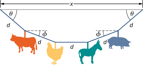
Hanging from the ceiling over a baby bed, well out of baby’s reach, is a string with plastic shapes, as shown here. The string is taut (there is no slack), as shown by the straight segments. Each plastic shape has the same mass m, and they are equally spaced by a distance d, as shown. The angles labeled [latex]\theta[/latex] describe the angle formed by the end of the string and the ceiling at each end. The center length of sting is horizontal. The remaining two segments each form an angle with the horizontal, labeled [latex]\varphi[/latex]. Let [latex]{T}_{1}[/latex] be the tension in the leftmost section of the string, [latex]{T}_{2}[/latex] be the tension in the section adjacent to it, and [latex]{T}_{3}[/latex] be the tension in the horizontal segment. (a) Find an equation for the tension in each section of the string in terms of the variables m, g, and [latex]\theta[/latex]. (b) Find the angle [latex]\varphi[/latex] in terms of the angle [latex]\theta[/latex]. (c) If [latex]\theta =5.10^\circ[/latex], what is the value of [latex]\varphi[/latex]? (d) Find the distance x between the endpoints in terms of d and [latex]\theta[/latex].
Show Solution
a. [latex]{T}_{1}=\frac{2mg}{\text{sin}\,\theta }[/latex], [latex]{T}_{2}=\frac{mg}{\text{sin}(\text{arctan}(\frac{1}{2}\text{tan}\,\theta ))}[/latex], [latex]{T}_{3}=\frac{2mg}{\text{tan}\,\theta };[/latex] b. [latex]\varphi =\text{arctan}(\frac{1}{2}\text{tan}\,\theta )[/latex]; c. [latex]2.56^\circ[/latex]; (d) [latex]x=d(2\,\text{cos}\,\theta +2\,\text{cos}(\text{arctan}(\frac{1}{2}\text{tan}\,\theta ))+1)[/latex]
A bullet shot from a rifle has mass of 10.0 g and travels to the right at 350 m/s. It strikes a target, a large bag of sand, penetrating it a distance of 34.0 cm. Find the magnitude and direction of the retarding force that slows and stops the bullet.
An object is acted on by three simultaneous forces: [latex]{\mathbf{\overset{\to }{F}}}_{1}=(-3.00\mathbf{\hat{i}}+2.00\mathbf{\hat{j}})\,\text{N}[/latex], [latex]{\mathbf{\overset{\to }{F}}}_{2}=(6.00\mathbf{\hat{i}}-4.00\mathbf{\hat{j}})\,\text{N}[/latex], and [latex]{\mathbf{\overset{\to }{F}}}_{3}=(2.00\mathbf{\hat{i}}+5.00\mathbf{\hat{j}})\,\text{N}[/latex]. The object experiences acceleration of [latex]4.23\,{\text{m/s}}^{2}[/latex]. (a) Find the acceleration vector in terms of m. (b) Find the mass of the object. (c) If the object begins from rest, find its speed after 5.00 s. (d) Find the components of the velocity of the object after 5.00 s.
Show Solution
a. [latex]\mathbf{\overset{\to }{a}}=(\frac{5.00}{m}\mathbf{\hat{i}}+\frac{3.00}{m}\mathbf{\hat{j}})\,\text{m}\text{/}{\text{s}}^{2};[/latex] b. 1.38 kg; c. 21.2 m/s; d. [latex]\mathbf{\overset{\to }{v}}=(18.1\mathbf{\hat{i}}+10.9\mathbf{\hat{j}})\,\text{m}\text{/}{\text{s}}^{2}[/latex]
In a particle accelerator, a proton has mass [latex]1.67\times {10}^{-27}\,\text{kg}[/latex] and an initial speed of [latex]2.00\times {10}^{5}\,\text{m}\text{/}\text{s.}[/latex] It moves in a straight line, and its speed increases to [latex]9.00\times {10}^{5}\,\text{m}\text{/}\text{s}[/latex] in a distance of 10.0 cm. Assume that the acceleration is constant. Find the magnitude of the force exerted on the proton.
A drone is being directed across a frictionless ice-covered lake. The mass of the drone is 1.50 kg, and its velocity is [latex]3.00\mathbf{\hat{i}}\text{m}\text{/}\text{s}[/latex]. After 10.0 s, the velocity is [latex]9.00\mathbf{\hat{i}}+4.00\mathbf{\hat{j}}\text{m}\text{/}\text{s}[/latex]. If a constant force in the horizontal direction is causing this change in motion, find (a) the components of the force and (b) the magnitude of the force.
Show Solution
a. [latex]0.900\mathbf{\hat{i}}+0.600\mathbf{\hat{j}}\,\text{N}[/latex]; b. 1.08 N