
Geometric Optics and Image Formation
Spherical Mirrors
Samuel J. Ling; Jeff Sanny; and William Moebs
Learning Objectives
By the end of this section, you will be able to:
- Describe image formation by spherical mirrors.
- Use ray diagrams and the mirror equation to calculate the properties of an image in a spherical mirror.
The image in a plane mirror has the same size as the object, is upright, and is the same distance behind the mirror as the object is in front of the mirror. A curved mirror, on the other hand, can form images that may be larger or smaller than the object and may form either in front of the mirror or behind it. In general, any curved surface will form an image, although some images make be so distorted as to be unrecognizable (think of fun house mirrors).
Because curved mirrors can create such a rich variety of images, they are used in many optical devices that find many uses. We will concentrate on spherical mirrors for the most part, because they are easier to manufacture than mirrors such as parabolic mirrors and so are more common.
Curved Mirrors
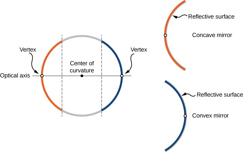
We can define two general types of spherical mirrors. If the reflecting surface is the outer side of the sphere, the mirror is called a convex mirror. If the inside surface is the reflecting surface, it is called a concave mirror.
Symmetry is one of the major hallmarks of many optical devices, including mirrors and lenses. The symmetry axis of such optical elements is often called the principal axis or optical axis. For a spherical mirror, the optical axis passes through the mirror’s center of curvature and the mirror’s vertex, as shown in (Figure).
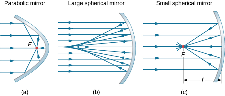
Consider rays that are parallel to the optical axis of a parabolic mirror, as shown in part (a) of (Figure). Following the law of reflection, these rays are reflected so that they converge at a point, called the focal point. Part (b) of this figure shows a spherical mirror that is large compared with its radius of curvature. For this mirror, the reflected rays do not cross at the same point, so the mirror does not have a well-defined focal point. This is called spherical aberration and results in a blurred image of an extended object. Part (c) shows a spherical mirror that is small compared to its radius of curvature. This mirror is a good approximation of a parabolic mirror, so rays that arrive parallel to the optical axis are reflected to a well-defined focal point. The distance along the optical axis from the mirror to the focal point is called the focal length of the mirror.
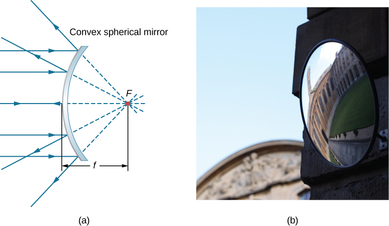
A convex spherical mirror also has a focal point, as shown in (Figure). Incident rays parallel to the optical axis are reflected from the mirror and seem to originate from point F at focal length f behind the mirror. Thus, the focal point is virtual because no real rays actually pass through it; they only appear to originate from it.
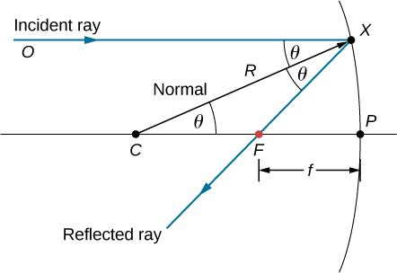
How does the focal length of a mirror relate to the mirror’s radius of curvature? (Figure) shows a single ray that is reflected by a spherical concave mirror. The incident ray is parallel to the optical axis. The point at which the reflected ray crosses the optical axis is the focal point. Note that all incident rays that are parallel to the optical axis are reflected through the focal point—we only show one ray for simplicity. We want to find how the focal length FP (denoted by f) relates to the radius of curvature of the mirror, R, whose length is  . The law of reflection tells us that angles OXC and CXF are the same, and because the incident ray is parallel to the optical axis, angles OXC and XCP are also the same. Thus, triangle CXF is an isosceles triangle with
  . If the angle
  is small (so that
  ; this is called the “small-angle approximation”), then
  or
or  . Inserting this into the equation for the radius R, we get

In other words, in the small-angle approximation, the focal length f of a concave spherical mirror is half of its radius of curvature, R:

In this chapter, we assume that the small-angle approximation (also called the paraxial approximation) is always valid. In this approximation, all rays are paraxial rays, which means that they make a small angle with the optical axis and are at a distance much less than the radius of curvature from the optical axis. In this case, their angles of reflection are small angles, so  .
.
Using Ray Tracing to Locate Images
To find the location of an image formed by a spherical mirror, we first use ray tracing, which is the technique of drawing rays and using the law of reflection to determine the reflected rays (later, for lenses, we use the law of refraction to determine refracted rays). Combined with some basic geometry, we can use ray tracing to find the focal point, the image location, and other information about how a mirror manipulates light. In fact, we already used ray tracing above to locate the focal point of spherical mirrors, or the image distance of flat mirrors. To locate the image of an object, you must locate at least two points of the image. Locating each point requires drawing at least two rays from a point on the object and constructing their reflected rays. The point at which the reflected rays intersect, either in real space or in virtual space, is where the corresponding point of the image is located. To make ray tracing easier, we concentrate on four “principal” rays whose reflections are easy to construct.
(Figure) shows a concave mirror and a convex mirror, each with an arrow-shaped object in front of it. These are the objects whose images we want to locate by ray tracing. To do so, we draw rays from point Q that is on the object but not on the optical axis. We choose to draw our ray from the tip of the object. Principal ray 1 goes from point Q and travels parallel to the optical axis. The reflection of this ray must pass through the focal point, as discussed above. Thus, for the concave mirror, the reflection of principal ray 1 goes through focal point F, as shown in part (b) of the figure. For the convex mirror, the backward extension of the reflection of principal ray 1 goes through the focal point (i.e., a virtual focus). Principal ray 2 travels first on the line going through the focal point and then is reflected back along a line parallel to the optical axis. Principal ray 3 travels toward the center of curvature of the mirror, so it strikes the mirror at normal incidence and is reflected back along the line from which it came. Finally, principal ray 4 strikes the vertex of the mirror and is reflected symmetrically about the optical axis.
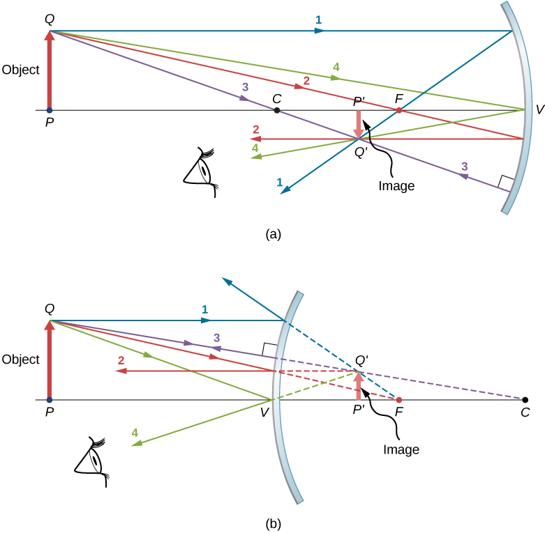
The four principal rays intersect at point  , which is where the image of point Q is located. To locate point , drawing any two of these principle rays would suffice. We are thus free to choose whichever of the principal rays we desire to locate the image. Drawing more than two principal rays is sometimes useful to verify that the ray tracing is correct.
To completely locate the extended image, we need to locate a second point in the image, so that we know how the image is oriented. To do this, we trace the principal rays from the base of the object. In this case, all four principal rays run along the optical axis, reflect from the mirror, and then run back along the optical axis. The difficulty is that, because these rays are collinear, we cannot determine a unique point where they intersect. All we know is that the base of the image is on the optical axis. However, because the mirror is symmetrical from top to bottom, it does not change the vertical orientation of the object. Thus, because the object is vertical, the image must be vertical. Therefore, the image of the base of the object is on the optical axis directly above the image of the tip, as drawn in the figure.
For the concave mirror, the extended image in this case forms between the focal point and the center of curvature of the mirror. It is inverted with respect to the object, is a real image, and is smaller than the object. Were we to move the object closer to or farther from the mirror, the characteristics of the image would change. For example, we show, as a later exercise, that an object placed between a concave mirror and its focal point leads to a virtual image that is upright and larger than the object. For the convex mirror, the extended image forms between the focal point and the mirror. It is upright with respect to the object, is a virtual image, and is smaller than the object.
Summary of Ray-Tracing Rules
Ray tracing is very useful for mirrors. The rules for ray tracing are summarized here for reference:
- A ray travelling parallel to the optical axis of a spherical mirror is reflected along a line that goes through the focal point of the mirror (ray 1 in (Figure)).
- A ray travelling along a line that goes through the focal point of a spherical mirror is reflected along a line parallel to the optical axis of the mirror (ray 2 in (Figure)).
- A ray travelling along a line that goes through the center of curvature of a spherical mirror is reflected back along the same line (ray 3 in (Figure)).
- A ray that strikes the vertex of a spherical mirror is reflected symmetrically about the optical axis of the mirror (ray 4 in (Figure)).
We use ray tracing to illustrate how images are formed by mirrors and to obtain numerical information about optical properties of the mirror. If we assume that a mirror is small compared with its radius of curvature, we can also use algebra and geometry to derive a mirror equation, which we do in the next section. Combining ray tracing with the mirror equation is a good way to analyze mirror systems.
Image Formation by Reflection—The Mirror Equation
For a plane mirror, we showed that the image formed has the same height and orientation as the object, and it is located at the same distance behind the mirror as the object is in front of the mirror. Although the situation is a bit more complicated for curved mirrors, using geometry leads to simple formulas relating the object and image distances to the focal lengths of concave and convex mirrors.
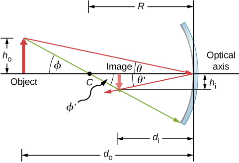
Consider the object OP shown in (Figure). The center of curvature of the mirror is labeled C and is a distance R from the vertex of the mirror, as marked in the figure. The object and image distances are labeled  and
and  , and the object and image heights are labeled
  and
and  , respectively. Because the angles
  and
and  are alternate interior angles, we know that they have the same magnitude. However, they must differ in sign if we measure angles from the optical axis, so
  . An analogous scenario holds for the angles and
  . The law of reflection tells us that they have the same magnitude, but their signs must differ if we measure angles from the optical axis. Thus,
  . Taking the tangent of the angles and , and using the property that
  , gives us

Similarly, taking the tangent of and gives

Combining these two results gives

After a little algebra, this becomes

No approximation is required for this result, so it is exact. However, as discussed above, in the small-angle approximation, the focal length of a spherical mirror is one-half the radius of curvature of the mirror, or  . Inserting this into (Figure) gives the mirror equation:

The mirror equation relates the image and object distances to the focal distance and is valid only in the small-angle approximation. Although it was derived for a concave mirror, it also holds for convex mirrors (proving this is left as an exercise). We can extend the mirror equation to the case of a plane mirror by noting that a plane mirror has an infinite radius of curvature. This means the focal point is at infinity, so the mirror equation simplifies to

which is the same as (Figure) obtained earlier.
Notice that we have been very careful with the signs in deriving the mirror equation. For a plane mirror, the image distance has the opposite sign of the object distance. Also, the real image formed by the concave mirror in (Figure) is on the opposite side of the optical axis with respect to the object. In this case, the image height should have the opposite sign of the object height. To keep track of the signs of the various quantities in the mirror equation, we now introduce a sign convention.
Sign convention for spherical mirrors
Using a consistent sign convention is very important in geometric optics. It assigns positive or negative values for the quantities that characterize an optical system. Understanding the sign convention allows you to describe an image without constructing a ray diagram. This text uses the following sign convention:
- The focal length f is positive for concave mirrors and negative for convex mirrors.
- The image distance is positive for real images and negative for virtual images.
Notice that rule 1 means that the radius of curvature of a spherical mirror can be positive or negative. What does it mean to have a negative radius of curvature? This means simply that the radius of curvature for a convex mirror is defined to be negative.
Image magnification
Let’s use the sign convention to further interpret the derivation of the mirror equation. In deriving this equation, we found that the object and image heights are related by

See (Figure). Both the object and the image formed by the mirror in (Figure) are real, so the object and image distances are both positive. The highest point of the object is above the optical axis, so the object height is positive. The image, however, is below the optical axis, so the image height is negative. Thus, this sign convention is consistent with our derivation of the mirror equation.
(Figure) in fact describes the linear magnification (often simply called “magnification”) of the image in terms of the object and image distances. We thus define the dimensionless magnification m as follows:

If m is positive, the image is upright, and if m is negative, the image is inverted. If  , the image is larger than the object, and if
  , the image is smaller than the object. With this definition of magnification, we get the following relation between the vertical and horizontal object and image distances:

This is a very useful relation because it lets you obtain the magnification of the image from the object and image distances, which you can obtain from the mirror equation.
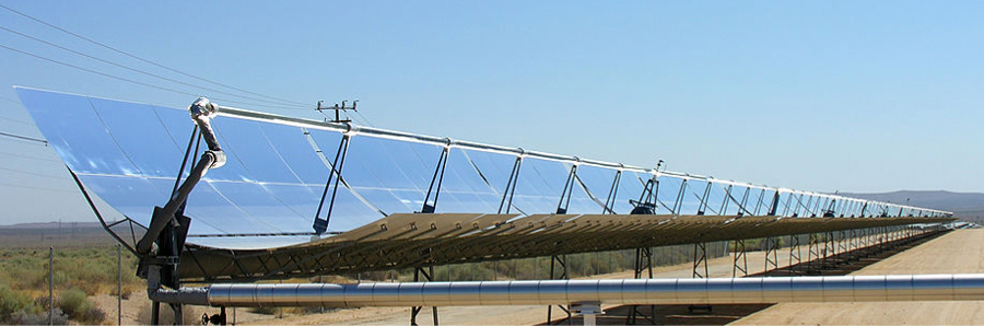
Solar Electric Generating System One of the solar technologies used today for generating electricity involves a device (called a parabolic trough or concentrating collector) that concentrates sunlight onto a blackened pipe that contains a fluid. This heated fluid is pumped to a heat exchanger, where the thermal energy is transferred to another system that is used to generate steam and eventually generates electricity through a conventional steam cycle. (Figure) shows such a working system in southern California. The real mirror is a parabolic cylinder with its focus located at the pipe; however, we can approximate the mirror as exactly one-quarter of a circular cylinder.
- If we want the rays from the sun to focus at 40.0 cm from the mirror, what is the radius of the mirror?
- What is the amount of sunlight concentrated onto the pipe, per meter of pipe length, assuming the insolation (incident solar radiation) is 900
 ?
? - If the fluid-carrying pipe has a 2.00-cm diameter, what is the temperature increase of the fluid per meter of pipe over a period of 1 minute? Assume that all solar radiation incident on the reflector is absorbed by the pipe, and that the fluid is mineral oil.
Strategy First identify the physical principles involved. Part (a) is related to the optics of spherical mirrors. Part (b) involves a little math, primarily geometry. Part (c) requires an understanding of heat and density.
Solution
- The sun is the object, so the object distance is essentially infinity:
 . The desired image distance is
  . We use the mirror equation to find the focal length of the mirror:

Thus, the radius of the mirror is .
. - The insolation is 900 . You must find the cross-sectional area A of the concave mirror, since the power delivered is 900
 . The mirror in this case is estimated as a quarter-section of a cylinder, so the area for a length L of the mirror is
  . The area for a length of 1.00 m is then

The insolation on the 1.00-m length of pipe is then

- The increase in temperature is given by
 . The mass m of the mineral oil in the one-meter section of pipe is

Therefore, the increase in temperature in one minute is

Significance An array of such pipes in the California desert can provide a thermal output of 250 MW on a sunny day, with fluids reaching temperatures as high as  . We are considering only one meter of pipe here and ignoring heat losses along the pipe.
Image in a Convex Mirror A keratometer is a device used to measure the curvature of the cornea of the eye, particularly for fitting contact lenses. Light is reflected from the cornea, which acts like a convex mirror, and the keratometer measures the magnification of the image. The smaller the magnification, the smaller the radius of curvature of the cornea. If the light source is 12 cm from the cornea and the image magnification is 0.032, what is the radius of curvature of the cornea?
Strategy If you find the focal length of the convex mirror formed by the cornea, then you know its radius of curvature (it’s twice the focal length). The object distance is  and the magnification is
  . First find the image distance and then solve for the focal length f.
Solution Start with the equation for magnification,  . Solving for and inserting the given values yields

where we retained an extra significant figure because this is an intermediate step in the calculation. Solve the mirror equation for the focal length f and insert the known values for the object and image distances. The result is

The radius of curvature is twice the focal length, so

Significance The focal length is negative, so the focus is virtual, as expected for a concave mirror and a real object. The radius of curvature found here is reasonable for a cornea. The distance from cornea to retina in an adult eye is about 2.0 cm. In practice, corneas may not be spherical, which complicates the job of fitting contact lenses. Note that the image distance here is negative, consistent with the fact that the image is behind the mirror. Thus, the image is virtual because no rays actually pass through it. In the problems and exercises, you will show that, for a fixed object distance, a smaller radius of curvature corresponds to a smaller the magnification.
Step 1. First make sure that image formation by a spherical mirror is involved.
Step 2. Determine whether ray tracing, the mirror equation, or both are required. A sketch is very useful even if ray tracing is not specifically required by the problem. Write symbols and known values on the sketch.
Step 3. Identify exactly what needs to be determined in the problem (identify the unknowns).
Step 4. Make a list of what is given or can be inferred from the problem as stated (identify the knowns).
Step 5. If ray tracing is required, use the ray-tracing rules listed near the beginning of this section.
Step 6. Most quantitative problems require using the mirror equation. Use the examples as guides for using the mirror equation.
Step 7. Check to see whether the answer makes sense. Do the signs of object distance, image distance, and focal length correspond with what is expected from ray tracing? Is the sign of the magnification correct? Are the object and image distances reasonable?
Departure from the Small-Angle Approximation
The small-angle approximation is a cornerstone of the above discussion of image formation by a spherical mirror. When this approximation is violated, then the image created by a spherical mirror becomes distorted. Such distortion is called aberration. Here we briefly discuss two specific types of aberrations: spherical aberration and coma.
Spherical aberration
Consider a broad beam of parallel rays impinging on a spherical mirror, as shown in (Figure).
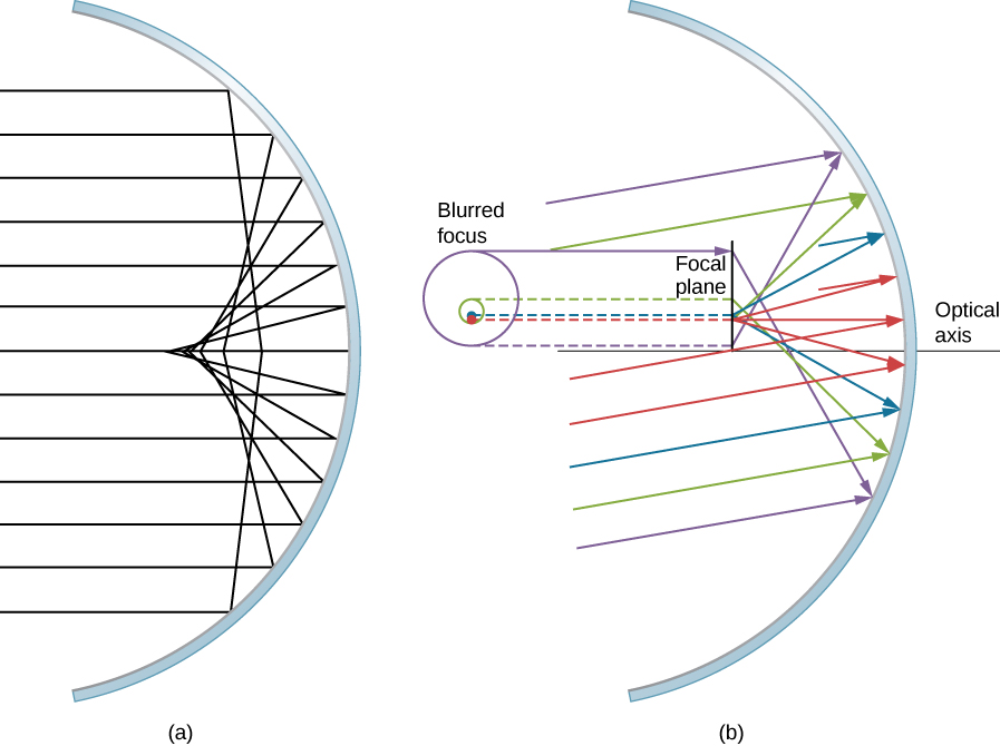
The farther from the optical axis the rays strike, the worse the spherical mirror approximates a parabolic mirror. Thus, these rays are not focused at the same point as rays that are near the optical axis, as shown in the figure. Because of spherical aberration, the image of an extended object in a spherical mirror will be blurred. Spherical aberrations are characteristic of the mirrors and lenses that we consider in the following section of this chapter (more sophisticated mirrors and lenses are needed to eliminate spherical aberrations).
Coma or comatic aberration
Coma is similar to spherical aberration, but arises when the incoming rays are not parallel to the optical axis, as shown in part (b) of (Figure). Recall that the small-angle approximation holds for spherical mirrors that are small compared to their radius. In this case, spherical mirrors are good approximations of parabolic mirrors. Parabolic mirrors focus all rays that are parallel to the optical axis at the focal point. However, parallel rays that are not parallel to the optical axis are focused at different heights and at different focal lengths, as show in part (b) of (Figure). Because a spherical mirror is symmetric about the optical axis, the various colored rays in this figure create circles of the corresponding color on the focal plane.
Although a spherical mirror is shown in part (b) of (Figure), comatic aberration occurs also for parabolic mirrors—it does not result from a breakdown in the small-angle approximation. Spherical aberration, however, occurs only for spherical mirrors and is a result of a breakdown in the small-angle approximation. We will discuss both coma and spherical aberration later in this chapter, in connection with telescopes.
Summary
- Spherical mirrors may be concave (converging) or convex (diverging).
- The focal length of a spherical mirror is one-half of its radius of curvature: .
- The mirror equation and ray tracing allow you to give a complete description of an image formed by a spherical mirror.
- Spherical aberration occurs for spherical mirrors but not parabolic mirrors; comatic aberration occurs for both types of mirrors.
Conceptual Questions
At what distance is an image always located: at  or f ?
Under what circumstances will an image be located at the focal point of a spherical lens or mirror?
when the object is at infinity; see the mirror equation
What is meant by a negative magnification? What is meant by a magnification whose absolute value is less than one?
Can an image be larger than the object even though its magnification is negative? Explain.
Yes, negative magnification simply means that the image is upside down; this does not prevent the image from being larger than the object. For instance, for a concave mirror, if distance to the object is larger than one focal distance but smaller than two focal distances the image will be inverted and magnified.
Problems
The following figure shows a light bulb between two spherical mirrors. One mirror produces a beam of light with parallel rays; the other keeps light from escaping without being put into the beam. Where is the filament of the light in relation to the focal point or radius of curvature of each mirror?
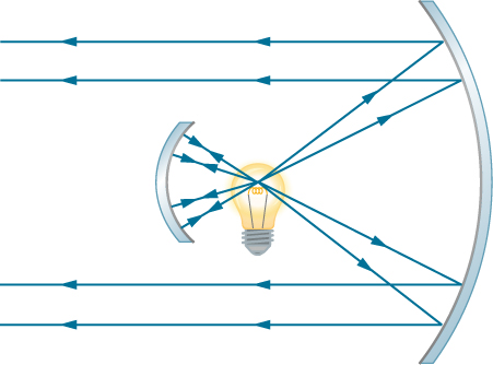
It is in the focal point of the big mirror and at the center of curvature of the small mirror.
Why are diverging mirrors often used for rearview mirrors in vehicles? What is the main disadvantage of using such a mirror compared with a flat one?
Some telephoto cameras use a mirror rather than a lens. What radius of curvature mirror is needed to replace a 800 mm-focal length telephoto lens?

Calculate the focal length of a mirror formed by the shiny back of a spoon that has a 3.00 cm radius of curvature.
Electric room heaters use a concave mirror to reflect infrared (IR) radiation from hot coils. Note that IR radiation follows the same law of reflection as visible light. Given that the mirror has a radius of curvature of 50.0 cm and produces an image of the coils 3.00 m away from the mirror, where are the coils?

Find the magnification of the heater element in the previous problem. Note that its large magnitude helps spread out the reflected energy.
What is the focal length of a makeup mirror that produces a magnification of 1.50 when a person’s face is 12.0 cm away? Explicitly show how you follow the steps in the (Figure).
Step 1: Image formation by a mirror is involved.
Step 2: Draw the problem set up when possible.
Step 3: Use thin-lens equations to solve this problem.
Step 4: Find f.
Step 5: Given:  .
.
Step 6: No ray tracing is needed.
Step 7: Using  . Then,
  .
.
Step 8: The image is virtual because the image distance is negative. The focal length is positive, so the mirror is concave.
A shopper standing 3.00 m from a convex security mirror sees his image with a magnification of 0.250. (a) Where is his image? (b) What is the focal length of the mirror? (c) What is its radius of curvature?
An object 1.50 cm high is held 3.00 cm from a person’s cornea, and its reflected image is measured to be 0.167 cm high. (a) What is the magnification? (b) Where is the image? (c) Find the radius of curvature of the convex mirror formed by the cornea. (Note that this technique is used by optometrists to measure the curvature of the cornea for contact lens fitting. The instrument used is called a keratometer, or curve measurer.)
a. for a convex mirror  ; b.
; b.  (behind the cornea);
c. 
Ray tracing for a flat mirror shows that the image is located a distance behind the mirror equal to the distance of the object from the mirror. This is stated as  , since this is a negative image distance (it is a virtual image). What is the focal length of a flat mirror?
Show that, for a flat mirror,  , given that the image is the same distance behind the mirror as the distance of the object from the mirror.

Use the law of reflection to prove that the focal length of a mirror is half its radius of curvature. That is, prove that . Note this is true for a spherical mirror only if its diameter is small compared with its radius of curvature.
Referring to the electric room heater considered in problem 5, calculate the intensity of IR radiation in projected by the concave mirror on a person 3.00 m away. Assume that the heating element radiates 1500 W and has an area of  , and that half of the radiated power is reflected and focused by the mirror.

Two mirrors are inclined at an angle of 60 and an object is placed at a point that is equidistant from the two mirrors. Use a protractor to draw rays accurately and locate all images. You may have to draw several figures so that that rays for different images do not clutter your drawing.
Two parallel mirrors are facing each other and are separated by a distance of 3 cm. A point object is placed between the mirrors 1 cm from one of the mirrors. Find the coordinates of all the images.

Glossary
- aberration
- distortion in an image caused by departures from the small-angle approximation
- coma
- similar to spherical aberration, but arises when the incoming rays are not parallel to the optical axis
- concave mirror
- spherical mirror with its reflecting surface on the inner side of the sphere; the mirror forms a “cave”
- convex mirror
- spherical mirror with its reflecting surface on the outer side of the sphere
- curved mirror
- mirror formed by a curved surface, such as spherical, elliptical, or parabolic
- focal length
- distance along the optical axis from the focal point to the optical element that focuses the light rays
- focal point
- for a converging lens or mirror, the point at which converging light rays cross; for a diverging lens or mirror, the point from which diverging light rays appear to originate
- linear magnification
- ratio of image height to object height
- optical axis
- axis about which the mirror is rotationally symmetric; you can rotate the mirror about this axis without changing anything
- small-angle approximation
- approximation that is valid when the size of a spherical mirror is significantly smaller than the mirror’s radius; in this approximation, spherical aberration is negligible and the mirror has a well-defined focal point
- spherical aberration
- distortion in the image formed by a spherical mirror when rays are not all focused at the same point
- vertex
- point where the mirror’s surface intersects with the optical axis
