
Diffraction
Diffraction Gratings
Samuel J. Ling; Jeff Sanny; and William Moebs
Learning Objectives
By the end of this section, you will be able to:
- Discuss the pattern obtained from diffraction gratings
- Explain diffraction grating effects
Analyzing the interference of light passing through two slits lays out the theoretical framework of interference and gives us a historical insight into Thomas Young’s experiments. However, most modern-day applications of slit interference use not just two slits but many, approaching infinity for practical purposes. The key optical element is called a diffraction grating, an important tool in optical analysis.
Diffraction Gratings: An Infinite Number of Slits
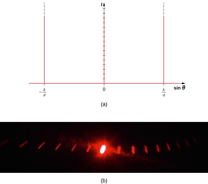
The analysis of multi-slit interference in Interference allows us to consider what happens when the number of slits N approaches infinity. Recall that  secondary maxima appear between the principal maxima. We can see there will be an infinite number of secondary maxima that appear, and an infinite number of dark fringes between them. This makes the spacing between the fringes, and therefore the width of the maxima, infinitesimally small. Furthermore, because the intensity of the secondary maxima is proportional to
  , it approaches zero so that the secondary maxima are no longer seen. What remains are only the principal maxima, now very bright and very narrow ((Figure)).
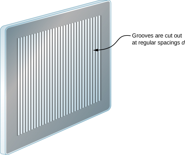
In reality, the number of slits is not infinite, but it can be very large—large enough to produce the equivalent effect. A prime example is an optical element called a diffraction grating. A diffraction grating can be manufactured by carving glass with a sharp tool in a large number of precisely positioned parallel lines, with untouched regions acting like slits ((Figure)). This type of grating can be photographically mass produced rather cheaply. Because there can be over 1000 lines per millimeter across the grating, when a section as small as a few millimeters is illuminated by an incoming ray, the number of illuminated slits is effectively infinite, providing for very sharp principal maxima.
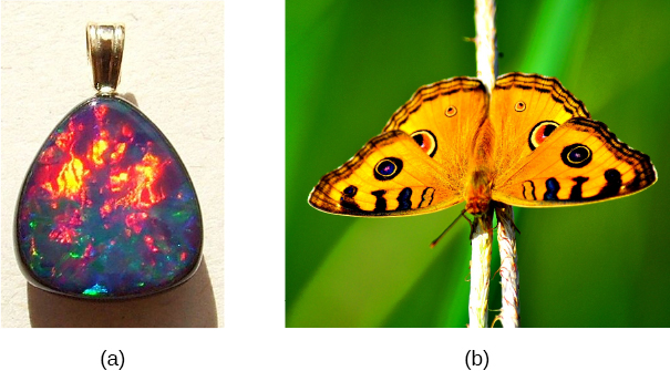
Diffraction gratings work both for transmission of light, as in (Figure), and for reflection of light, as on butterfly wings and the Australian opal in (Figure). Natural diffraction gratings also occur in the feathers of certain birds such as the hummingbird. Tiny, finger-like structures in regular patterns act as reflection gratings, producing constructive interference that gives the feathers colors not solely due to their pigmentation. This is called iridescence.
Applications of Diffraction Gratings
Where are diffraction gratings used in applications? Diffraction gratings are commonly used for spectroscopic dispersion and analysis of light. What makes them particularly useful is the fact that they form a sharper pattern than double slits do. That is, their bright fringes are narrower and brighter while their dark regions are darker. Diffraction gratings are key components of monochromators used, for example, in optical imaging of particular wavelengths from biological or medical samples. A diffraction grating can be chosen to specifically analyze a wavelength emitted by molecules in diseased cells in a biopsy sample or to help excite strategic molecules in the sample with a selected wavelength of light. Another vital use is in optical fiber technologies where fibers are designed to provide optimum performance at specific wavelengths. A range of diffraction gratings are available for selecting wavelengths for such use.
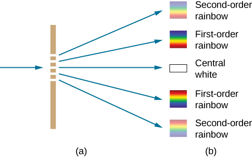
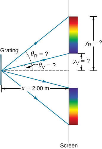
Calculating Typical Diffraction Grating Effects Diffraction gratings with 10,000 lines per centimeter are readily available. Suppose you have one, and you send a beam of white light through it to a screen 2.00 m away. (a) Find the angles for the first-order diffraction of the shortest and longest wavelengths of visible light (380 and 760 nm, respectively). (b) What is the distance between the ends of the rainbow of visible light produced on the screen for first-order interference? (See (Figure).)
 from the grating. The distances along the screen are measured perpendicular to the x-direction. In other words, the rainbow pattern extends out of the page.
(b) In a bird’s-eye view, the rainbow pattern can be seen on a table where the equipment is placed.
Strategy Once a value for the diffraction grating’s slit spacing d has been determined, the angles for the sharp lines can be found using the equation

Since there are 10,000 lines per centimeter, each line is separated by 1/10,000 of a centimeter. Once we know the angles, we an find the distances along the screen by using simple trigonometry.
Solution
- The distance between slits is
 Let us call the two angles
  for violet (380 nm) and
  for red (760 nm). Solving the equation

where for the first-order and
  Substituting these values gives

Thus the angle is

Similarly,

Thus the angle is

Notice that in both equations, we reported the results of these intermediate calculations to four significant figures to use with the calculation in part (b). - The distances on the secreen are labeled
 in (Figure). Notice that
  We can solve for
  That is,

and

The distance between them is therefore

Significance The large distance between the red and violet ends of the rainbow produced from the white light indicates the potential this diffraction grating has as a spectroscopic tool. The more it can spread out the wavelengths (greater dispersion), the more detail can be seen in a spectrum. This depends on the quality of the diffraction grating—it must be very precisely made in addition to having closely spaced lines.
Check Your Understanding If the line spacing of a diffraction grating d is not precisely known, we can use a light source with a well-determined wavelength to measure it. Suppose the first-order constructive fringe of the  emission line of hydrogen
  is measured at
  using a spectrometer with a diffraction grating. What is the line spacing of this grating?
 or 300 lines per millimeter
Take the same simulation we used for double-slit diffraction and try increasing the number of slits from  to
to  . The primary peaks become sharper, and the secondary peaks become less and less pronounced. By the time you reach the maximum number of
  , the system is behaving much like a diffraction grating.
Summary
- A diffraction grating consists of a large number of evenly spaced parallel slits that produce an interference pattern similar to but sharper than that of a double slit.
- Constructive interference occurs when
 where d is the distance between the slits,
  is the angle relative to the incident direction, and m is the order of the interference.
Problems
A diffraction grating has 2000 lines per centimeter. At what angle will the first-order maximum be for 520-nm-wavelength green light?

Find the angle for the third-order maximum for 580-nm-wavelength yellow light falling on a difraction grating having 1500 lines per centimeter.
How many lines per centimeter are there on a diffraction grating that gives a first-order maximum for 470-nm blue light at an angle of  ?
?

What is the distance between lines on a diffraction grating that produces a second-order maximum for 760-nm red light at an angle of  ?
?
Calculate the wavelength of light that has its second-order maximum at  when falling on a diffraction grating that has 5000 lines per centimeter.
707 nm
An electric current through hydrogen gas produces several distinct wavelengths of visible light. What are the wavelengths of the hydrogen spectrum, if they form first-order maxima at angles  and
and  when projected on a diffraction grating having 10,000 lines per centimeter?
(a) What do the four angles in the preceding problem become if a 5000-line per centimeter diffraction grating is used? (b) Using this grating, what would the angles be for the second-order maxima? (c) Discuss the relationship between integral reductions in lines per centimeter and the new angles of various order maxima.
a.  ,
,  ,
,  ,
,  ; b.
; b.  ,
,  ,
,  , ; c. Decreasing the number of lines per centimeter by a factor of x means that the angle for the x-order maximum is the same as the original angle for the first-order maximum.
What is the spacing between structures in a feather that acts as a reflection grating, giving that they produce a first-order maximum for 525-nm light at a  angle?
An opal such as that shown in (Figure) acts like a reflection grating with rows separated by about  If the opal is illuminated normally, (a) at what angle will red light be seen and (b) at what angle will blue light be seen?
a. using  b. using
At what angle does a diffraction grating produce a second-order maximum for light having a first-order maximum at  ?
?
(a) Find the maximum number of lines per centimeter a diffraction grating can have and produce a maximum for the smallest wavelength of visible light. (b) Would such a grating be useful for ultraviolet spectra? (c) For infrared spectra?
a. 26,300 lines/cm; b. yes; c. no
(a) Show that a 30,000 line per centimeter grating will not produce a maximum for visible light. (b) What is the longest wavelength for which it does produce a first-order maximum? (c) What is the greatest number of line per centimeter a diffraction grating can have and produce a complete second-order spectrum for visible light?
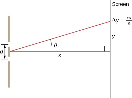
The analysis shown below also applies to diffraction gratings with lines separated by a distance d. What is the distance between fringes produced by a diffraction grating having 125 lines per centimeter for 600-nm light, if the screen is 1.50 m away? (Hint: The distance between adjacent fringes is  assuming the slit separation d is comparable to
  )
)

Glossary
- diffraction grating
- large number of evenly spaced parallel slits
