
Geometric Optics and Image Formation
Images Formed by Refraction
Samuel J. Ling; Jeff Sanny; and William Moebs
Learning Objectives
By the end of this section, you will be able to:
- Describe image formation by a single refracting surface
- Determine the location of an image and calculate its properties by using a ray diagram
- Determine the location of an image and calculate its properties by using the equation for a single refracting surface
When rays of light propagate from one medium to another, these rays undergo refraction, which is when light waves are bent at the interface between two media. The refracting surface can form an image in a similar fashion to a reflecting surface, except that the law of refraction (Snell’s law) is at the heart of the process instead of the law of reflection.
Refraction at a Plane Interface—Apparent Depth
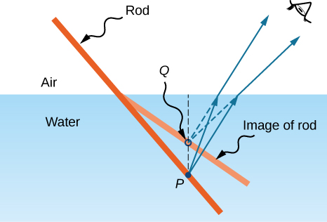
If you look at a straight rod partially submerged in water, it appears to bend at the surface ((Figure)). The reason behind this curious effect is that the image of the rod inside the water forms a little closer to the surface than the actual position of the rod, so it does not line up with the part of the rod that is above the water. The same phenomenon explains why a fish in water appears to be closer to the surface than it actually is.
To study image formation as a result of refraction, consider the following questions:
- What happens to the rays of light when they enter or pass through a different medium?
- Do the refracted rays originating from a single point meet at some point or diverge away from each other?
To be concrete, we consider a simple system consisting of two media separated by a plane interface ((Figure)). The object is in one medium and the observer is in the other. For instance, when you look at a fish from above the water surface, the fish is in medium 1 (the water) with refractive index 1.33, and your eye is in medium 2 (the air) with refractive index 1.00, and the surface of the water is the interface. The depth that you “see” is the image height  and is called the apparent depth. The actual depth of the fish is the object height
  .
.
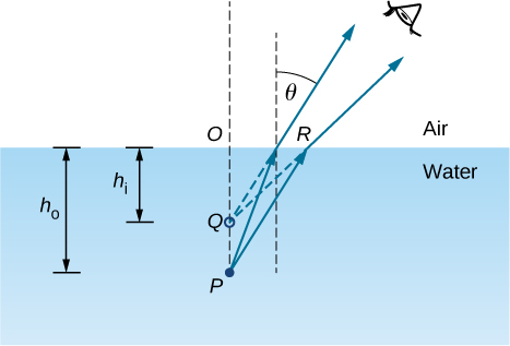
The apparent depth depends on the angle at which you view the image. For a view from above (the so-called “normal” view), we can approximate the refraction angle  to be small, and replace sin in Snell’s law by tan . With this approximation, you can use the triangles
  and
and  to show that the apparent depth is given by

The derivation of this result is left as an exercise. Thus, a fish appears at 3/4 of the real depth when viewed from above.
Refraction at a Spherical Interface
Spherical shapes play an important role in optics primarily because high-quality spherical shapes are far easier to manufacture than other curved surfaces. To study refraction at a single spherical surface, we assume that the medium with the spherical surface at one end continues indefinitely (a “semi-infinite” medium).
Refraction at a convex surface
Consider a point source of light at point P in front of a convex surface made of glass (see (Figure)). Let R be the radius of curvature,  be the refractive index of the medium in which object point P is located, and
  be the refractive index of the medium with the spherical surface. We want to know what happens as a result of refraction at this interface.
 .
.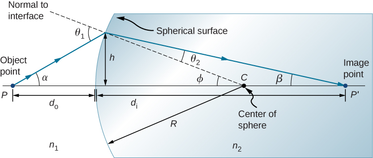
Because of the symmetry involved, it is sufficient to examine rays in only one plane. The figure shows a ray of light that starts at the object point P, refracts at the interface, and goes through the image point  . We derive a formula relating the object distance
  , the image distance
  , and the radius of curvature R.
Applying Snell’s law to the ray emanating from point P gives  . We work in the small-angle approximation, so
  and Snell’s law then takes the form

From the geometry of the figure, we see that

Inserting these expressions into Snell’s law gives

Using the diagram, we calculate the tangent of the angles  :
:

Again using the small-angle approximation, we find that  , so the above relationships become

Putting these angles into Snell’s law gives

We can write this more conveniently as

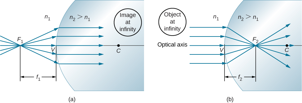
If the object is placed at a special point called the first focus, or the object focus  , then the image is formed at infinity, as shown in part (a) of (Figure).
We can find the location  of the first focus by setting
  in the preceding equation.


Similarly, we can define a second focus or image focus  where the image is formed for an object that is far away [part (b)]. The location of the second focus is obtained from (Figure) by setting
  :
:


Note that the object focus is at a different distance from the vertex than the image focus because  .
.
Sign convention for single refracting surfaces
Although we derived this equation for refraction at a convex surface, the same expression holds for a concave surface, provided we use the following sign convention:
 if surface is convex toward object; otherwise,
 if image is real and on opposite side from the object; otherwise,
Summary
This section explains how a single refracting interface forms images.
- When an object is observed through a plane interface between two media, then it appears at an apparent distance that differs from the actual distance :
 .
. - An image is formed by the refraction of light at a spherical interface between two media of indices of refraction and .
- Image distance depends on the radius of curvature of the interface, location of the object, and the indices of refraction of the media.
Conceptual Questions
Derive the formula for the apparent depth of a fish in a fish tank using Snell’s law.
Use a ruler and a protractor to find the image by refraction in the following cases. Assume an air-glass interface. Use a refractive index of 1 for air and of 1.5 for glass. (Hint: Use Snell’s law at the interface.)
(a) A point object located on the axis of a concave interface located at a point within the focal length from the vertex.
(b) A point object located on the axis of a concave interface located at a point farther than the focal length from the vertex.
(c) A point object located on the axis of a convex interface located at a point within the focal length from the vertex.
(d) A point object located on the axis of a convex interface located at a point farther than the focal length from the vertex.
(e) Repeat (a)–(d) for a point object off the axis.
answers may vary
Problems
An object is located in air 30 cm from the vertex of a concave surface made of glass with a radius of curvature 10 cm. Where does the image by refraction form and what is its magnification? Use  and
and  .
.
An object is located in air 30 cm from the vertex of a convex surface made of glass with a radius of curvature 80 cm. Where does the image by refraction form and what is its magnification?

An object is located in water 15 cm from the vertex of a concave surface made of glass with a radius of curvature 10 cm. Where does the image by refraction form and what is its magnification? Use  and .
and .
An object is located in water 30 cm from the vertex of a convex surface made of Plexiglas with a radius of curvature of 80 cm. Where does the image form by refraction and what is its magnification? and  .
.

An object is located in air 5 cm from the vertex of a concave surface made of glass with a radius of curvature 20 cm. Where does the image form by refraction and what is its magnification? Use and .
Derive the spherical interface equation for refraction at a concave surface. (Hint: Follow the derivation in the text for the convex surface.)
proof
Glossary
- apparent depth
- depth at which an object is perceived to be located with respect to an interface between two media
- first focus or object focus
- object located at this point will result in an image created at infinity on the opposite side of a spherical interface between two media
- second focus or image focus
- for a converging interface, the point where a bundle of parallel rays refracting at a spherical interface; for a diverging interface, the point at which the backward continuation of the refracted rays will converge between two media will focus
