
Geometric Optics and Image Formation
Images Formed by Plane Mirrors
Samuel J. Ling; Jeff Sanny; and William Moebs
Learning Objectives
By the end of this section, you will be able to:
- Describe how an image is formed by a plane mirror.
- Distinguish between real and virtual images.
- Find the location and characterize the orientation of an image created by a plane mirror.
You only have to look as far as the nearest bathroom to find an example of an image formed by a mirror. Images in a plane mirror are the same size as the object, are located behind the mirror, and are oriented in the same direction as the object (i.e., “upright”).
To understand how this happens, consider (Figure). Two rays emerge from point P, strike the mirror, and reflect into the observer’s eye. Note that we use the law of reflection to construct the reflected rays. If the reflected rays are extended backward behind the mirror (see dashed lines in (Figure)), they seem to originate from point Q. This is where the image of point P is located. If we repeat this process for point  , we obtain its image at point
  . You should convince yourself by using basic geometry that the image height (the distance from Q to ) is the same as the object height (the distance from P to ). By forming images of all points of the object, we obtain an upright image of the object behind the mirror.
gives the image point . The image height is thus the same as the object height, the image is upright, and the object distance  is the same as the image distance
  . (credit: modification of work by Kevin Dufendach)
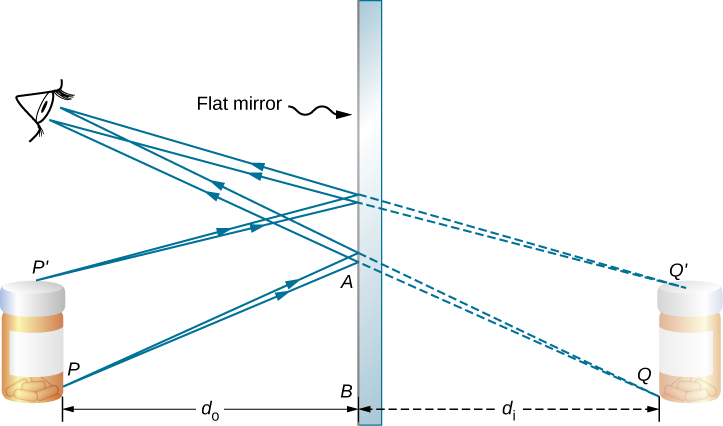
Notice that the reflected rays appear to the observer to come directly from the image behind the mirror. In reality, these rays come from the points on the mirror where they are reflected. The image behind the mirror is called a virtual image because it cannot be projected onto a screen—the rays only appear to originate from a common point behind the mirror. If you walk behind the mirror, you cannot see the image, because the rays do not go there. However, in front of the mirror, the rays behave exactly as if they come from behind the mirror, so that is where the virtual image is located.
Later in this chapter, we discuss real images; a real image can be projected onto a screen because the rays physically go through the image. You can certainly see both real and virtual images. The difference is that a virtual image cannot be projected onto a screen, whereas a real image can.
Locating an Image in a Plane Mirror
The law of reflection tells us that the angle of incidence is the same as the angle of reflection. Applying this to triangles PAB and QAB in (Figure) and using basic geometry shows that they are congruent triangles. This means that the distance PB from the object to the mirror is the same as the distance BQ from the mirror to the image. The object distance (denoted ) is the distance from the mirror to the object (or, more generally, from the center of the optical element that creates its image). Similarly, the image distance (denoted ) is the distance from the mirror to the image (or, more generally, from the center of the optical element that creates it). If we measure distances from the mirror, then the object and image are in opposite directions, so for a plane mirror, the object and image distances should have the opposite signs:

An extended object such as the container in (Figure) can be treated as a collection of points, and we can apply the method above to locate the image of each point on the extended object, thus forming the extended image.
Multiple Images
If an object is situated in front of two mirrors, you may see images in both mirrors. In addition, the image in the first mirror may act as an object for the second mirror, so the second mirror may form an image of the image. If the mirrors are placed parallel to each other and the object is placed at a point other than the midpoint between them, then this process of image-of-an-image continues without end, as you may have noticed when standing in a hallway with mirrors on each side. This is shown in (Figure), which shows three images produced by the blue object. Notice that each reflection reverses front and back, just like pulling a right-hand glove inside out produces a left-hand glove (this is why a reflection of your right hand is a left hand). Thus, the fronts and backs of images 1 and 2 are both inverted with respect to the object, and the front and back of image 3 is inverted with respect to image 2, which is the object for image 3.
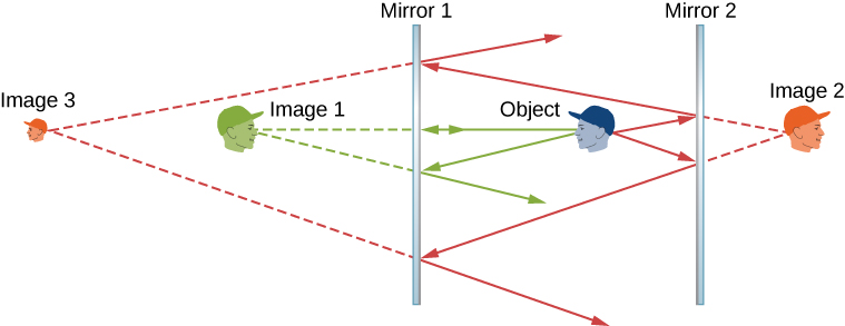
You may have noticed that image 3 is smaller than the object, whereas images 1 and 2 are the same size as the object. The ratio of the image height with respect to the object height is called magnification. More will be said about magnification in the next section.
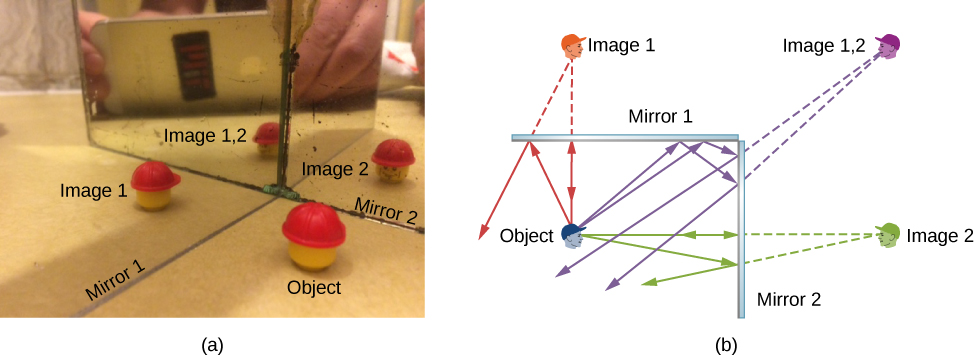
Infinite reflections may terminate. For instance, two mirrors at right angles form three images, as shown in part (a) of (Figure). Images 1 and 2 result from rays that reflect from only a single mirror, but image 1,2 is formed by rays that reflect from both mirrors. This is shown in the ray-tracing diagram in part (b) of (Figure). To find image 1,2, you have to look behind the corner of the two mirrors.
Summary
- A plane mirror always forms a virtual image (behind the mirror).
- The image and object are the same distance from a flat mirror, the image size is the same as the object size, and the image is upright.
Conceptual Questions
What are the differences between real and virtual images? How can you tell (by looking) whether an image formed by a single lens or mirror is real or virtual?
Virtual image cannot be projected on a screen. You cannot distinguish a real image from a virtual image simply by judging from the image perceived with your eye.
Can you see a virtual image? Explain your response.
Can you photograph a virtual image?
Yes, you can photograph a virtual image. For example, if you photograph your reflection from a plane mirror, you get a photograph of a virtual image. The camera focuses the light that enters its lens to form an image; whether the source of the light is a real object or a reflection from mirror (i.e., a virtual image) does not matter.
Can you project a virtual image onto a screen?
Is it necessary to project a real image onto a screen to see it?
No, you can see the real image the same way you can see the virtual image. The retina of your eye effectively serves as a screen.
Devise an arrangement of mirrors allowing you to see the back of your head. What is the minimum number of mirrors needed for this task?
If you wish to see your entire body in a flat mirror (from head to toe), how tall should the mirror be? Does its size depend upon your distance away from the mirror? Provide a sketch.
The mirror should be half your size and its top edge should be at the level of your eyes. The size does not depend on your distance from the mirror.
Problems
Consider a pair of flat mirrors that are positioned so that they form an angle of 120 . An object is placed on the bisector between the mirrors. Construct a ray diagram as in (Figure) to show how many images are formed.
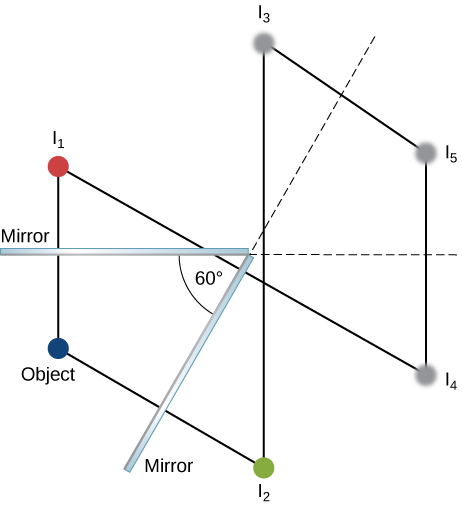
Consider a pair of flat mirrors that are positioned so that they form an angle of 60. An object is placed on the bisector between the mirrors. Construct a ray diagram as in (Figure) to show how many images are formed.
By using more than one flat mirror, construct a ray diagram showing how to create an inverted image.
Glossary
- plane mirror
- plane (flat) reflecting surface
- image distance
- distance of the image from the central axis of the optical element that produces the image
- magnification
- ratio of image size to object size
- object distance
- distance of the object from the central axis of the optical element that produces its image
- real image
- image that can be projected onto a screen because the rays physically go through the image
- virtual image
- image that cannot be projected on a screen because the rays do not physically go through the image, they only appear to originate from the image
