
Chapter 27 Wave Optics
27.7 Thin Film Interference
Summary
- Discuss the rainbow formation by thin films.
The bright colors seen in an oil slick floating on water or in a sunlit soap bubble are caused by interference. The brightest colors are those that interfere constructively. This interference is between light reflected from different surfaces of a thin film; thus, the effect is known as thin film interference. As noticed before, interference effects are most prominent when light interacts with something having a size similar to its wavelength. A thin film is one having a thickness [latex]{t}[/latex] smaller than a few times the wavelength of light, [latex]{\lambda}[/latex]. Since color is associated indirectly with [latex]{\lambda}[/latex] and since all interference depends in some way on the ratio of [latex]{\lambda}[/latex] to the size of the object involved, we should expect to see different colors for different thicknesses of a film, as in Figure 1.
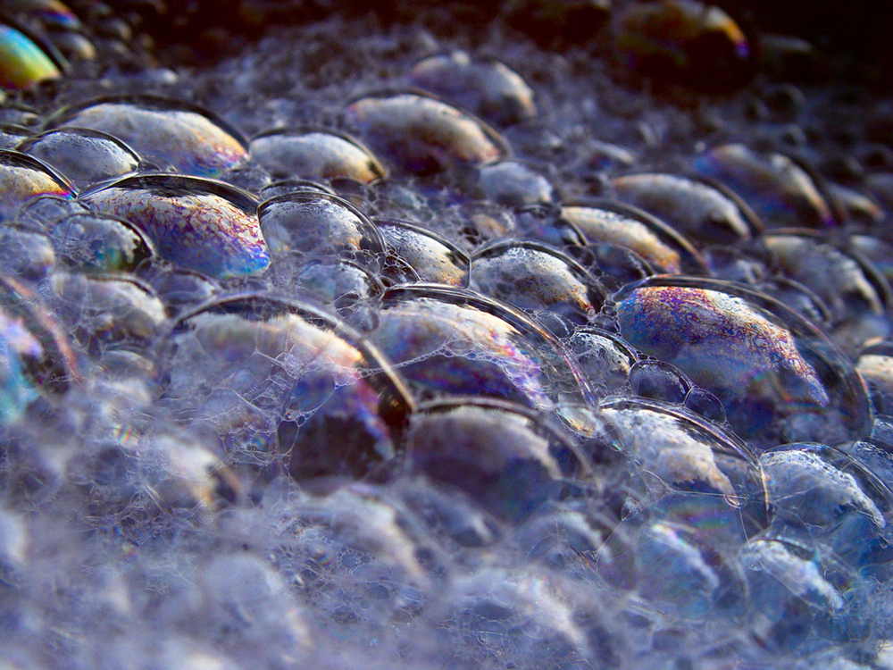
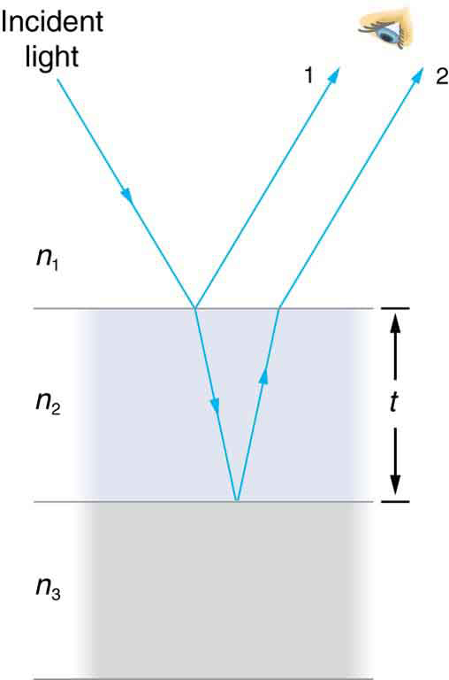
What causes thin film interference? Figure 2 shows how light reflected from the top and bottom surfaces of a film can interfere. Incident light is only partially reflected from the top surface of the film (ray 1). The remainder enters the film and is itself partially reflected from the bottom surface. Part of the light reflected from the bottom surface can emerge from the top of the film (ray 2) and interfere with light reflected from the top (ray 1). Since the ray that enters the film travels a greater distance, it may be in or out of phase with the ray reflected from the top. However, consider for a moment, again, the bubbles in Figure 1. The bubbles are darkest where they are thinnest. Furthermore, if you observe a soap bubble carefully, you will note it gets dark at the point where it breaks. For very thin films, the difference in path lengths of ray 1 and ray 2 in Figure 2 is negligible; so why should they interfere destructively and not constructively? The answer is that a phase change can occur upon reflection. The rule is as follows:
When light reflects from a medium having an index of refraction greater than that of the medium in which it is traveling, a [latex]{180^{\circ}}[/latex] phase change (or a [latex]{\lambda /2}[/latex] shift) occurs.
If the film in Figure 2 is a soap bubble (essentially water with air on both sides), then there is a [latex]{\lambda /2}[/latex] shift for ray 1 and none for ray 2. Thus, when the film is very thin, the path length difference between the two rays is negligible, they are exactly out of phase, and destructive interference will occur at all wavelengths and so the soap bubble will be dark here.
The thickness of the film relative to the wavelength of light is the other crucial factor in thin film interference. Ray 2 in Figure 2 travels a greater distance than ray 1. For light incident perpendicular to the surface, ray 2 travels a distance approximately [latex]{2t}[/latex] farther than ray 1. When this distance is an integral or half-integral multiple of the wavelength in the medium ([latex]{\lambda _n = \lambda /n}[/latex], where [latex]{\lambda}[/latex] is the wavelength in vacuum and [latex]{n}[/latex] is the index of refraction), constructive or destructive interference occurs, depending also on whether there is a phase change in either ray.
Example 1: Calculating Non-reflective Lens Coating Using Thin Film Interference
Sophisticated cameras use a series of several lenses. Light can reflect from the surfaces of these various lenses and degrade image clarity. To limit these reflections, lenses are coated with a thin layer of magnesium fluoride that causes destructive thin film interference. What is the thinnest this film can be, if its index of refraction is 1.38 and it is designed to limit the reflection of 550-nm light, normally the most intense visible wavelength? The index of refraction of glass is 1.52.
Strategy
Refer to Figure 2 and use [latex]{n_1 = 100}[/latex] for air, [latex]{n_2 = 1.38}[/latex], and [latex]{n_3 = 1.52}[/latex]. Both ray 1 and ray 2 will have a [latex]{\lambda /2}[/latex] shift upon reflection. Thus, to obtain destructive interference, ray 2 will need to travel a half wavelength farther than ray 1. For rays incident perpendicularly, the path length difference is [latex]{2t}[/latex].
Solution
To obtain destructive interference here,
where [latex]{\lambda n_2}[/latex] is the wavelength in the film and is given by [latex]{\lambda _{n_2} = \frac{\lambda}{n_2}}[/latex].
Thus,
Solving for [latex]{t}[/latex] and entering known values yields
Discussion
Films such as the one in this example are most effective in producing destructive interference when the thinnest layer is used, since light over a broader range of incident angles will be reduced in intensity. These films are called non-reflective coatings; this is only an approximately correct description, though, since other wavelengths will only be partially cancelled. Non-reflective coatings are used in car windows and sunglasses.
Thin film interference is most constructive or most destructive when the path length difference for the two rays is an integral or half-integral wavelength, respectively. That is, for rays incident perpendicularly, [latex]{2t = \lambda _n , \; 2 \lambda _n , \; 3 \lambda _n , \;\dots}[/latex]. To know whether interference is constructive or destructive, you must also determine if there is a phase change upon reflection. Thin film interference thus depends on film thickness, the wavelength of light, and the refractive indices. For white light incident on a film that varies in thickness, you will observe rainbow colors of constructive interference for various wavelengths as the thickness varies.
Example 2: Soap Bubbles: More Than One Thickness can be Constructive
(a) What are the three smallest thicknesses of a soap bubble that produce constructive interference for red light with a wavelength of 650 nm? The index of refraction of soap is taken to be the same as that of water. (b) What three smallest thicknesses will give destructive interference?
Strategy and Concept
Use Figure 2 to visualize the bubble. Note that [latex]{n_1 = n_3 = 1.00}[/latex] for air, and [latex]{n_2 = 1.333}[/latex] for soap (equivalent to water). There is a [latex]{\lambda /2}[/latex] shift for ray 1 reflected from the top surface of the bubble, and no shift for ray 2 reflected from the bottom surface. To get constructive interference, then, the path length difference ([latex]{2t}[/latex]) must be a half-integral multiple of the wavelength—the first three being [latex]{\lambda _n /2 , \; 3 \lambda _n/2}[/latex], and [latex]{5 \lambda _n /2}[/latex]. To get destructive interference, the path length difference must be an integral multiple of the wavelength—the first three being [latex]{0 , \;\lambda _n}[/latex], and [latex]{2 \lambda _n}[/latex].
Solution for (a)
Constructive interference occurs here when
The smallest constructive thickness [latex]{t_c}[/latex] thus is
The next thickness that gives constructive interference is [latex]{{t ^{\prime}} _c = 3 \lambda _n /4}[/latex], so that
Finally, the third thickness producing constructive interference is [latex]{{t^{\prime \prime}} _c \le 5 \lambda _n /4}[/latex], so that
Solution for (b)
For destructive interference, the path length difference here is an integral multiple of the wavelength. The first occurs for zero thickness, since there is a phase change at the top surface. That is,
The first non-zero thickness producing destructive interference is
Substituting known values gives
Finally, the third destructive thickness is [latex]{{2t ^{\prime \prime}} _d = 2 \lambda _n}[/latex], so that
Discussion
If the bubble was illuminated with pure red light, we would see bright and dark bands at very uniform increases in thickness. First would be a dark band at 0 thickness, then bright at 122 nm thickness, then dark at 244 nm, bright at 366 nm, dark at 488 nm, and bright at 610 nm. If the bubble varied smoothly in thickness, like a smooth wedge, then the bands would be evenly spaced.
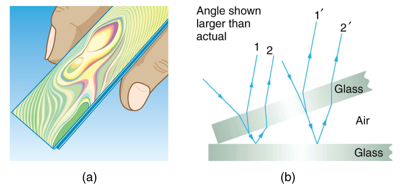
Another example of thin film interference can be seen when microscope slides are separated (see Figure 3). The slides are very flat, so that the wedge of air between them increases in thickness very uniformly. A phase change occurs at the second surface but not the first, and so there is a dark band where the slides touch. The rainbow colors of constructive interference repeat, going from violet to red again and again as the distance between the slides increases. As the layer of air increases, the bands become more difficult to see, because slight changes in incident angle have greater effects on path length differences. If pure-wavelength light instead of white light is used, then bright and dark bands are obtained rather than repeating rainbow colors.
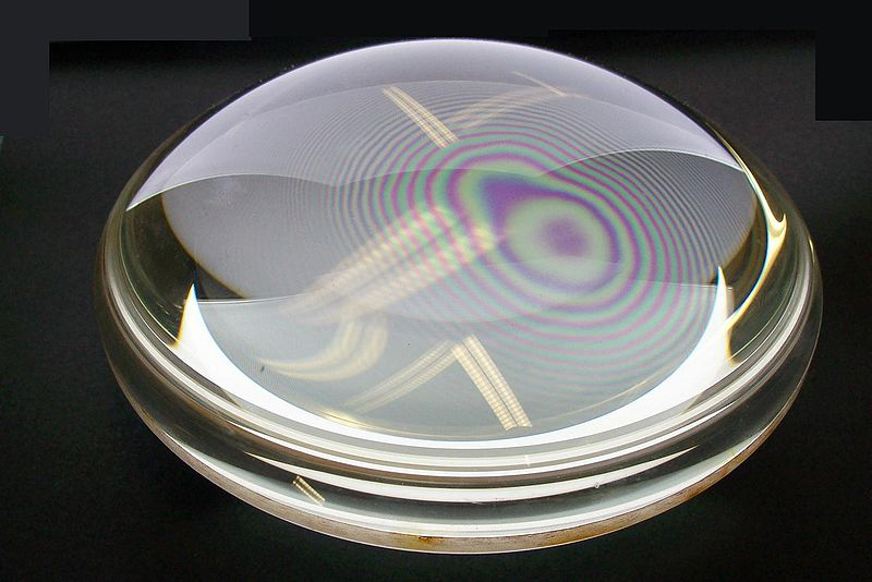
An important application of thin film interference is found in the manufacturing of optical instruments. A lens or mirror can be compared with a master as it is being ground, allowing it to be shaped to an accuracy of less than a wavelength over its entire surface. Figure 4 illustrates the phenomenon called Newton’s rings, which occurs when the plane surfaces of two lenses are placed together. (The circular bands are called Newton’s rings because Isaac Newton described them and their use in detail. Newton did not discover them; Robert Hooke did, and Newton did not believe they were due to the wave character of light.) Each successive ring of a given color indicates an increase of only one wavelength in the distance between the lens and the blank, so that great precision can be obtained. Once the lens is perfect, there will be no rings.
The wings of certain moths and butterflies have nearly iridescent colors due to thin film interference. In addition to pigmentation, the wing’s color is affected greatly by constructive interference of certain wavelengths reflected from its film-coated surface. Car manufacturers are offering special paint jobs that use thin film interference to produce colors that change with angle. This expensive option is based on variation of thin film path length differences with angle. Security features on credit cards, banknotes, driving licenses and similar items prone to forgery use thin film interference, diffraction gratings, or holograms. Australia led the way with dollar bills printed on polymer with a diffraction grating security feature making the currency difficult to forge. Other countries such as New Zealand and Taiwan are using similar technologies, while the United States currency includes a thin film interference effect.
Making Connections: Take-Home Experiment—Thin Film Interference
One feature of thin film interference and diffraction gratings is that the pattern shifts as you change the angle at which you look or move your head. Find examples of thin film interference and gratings around you. Explain how the patterns change for each specific example. Find examples where the thickness changes giving rise to changing colors. If you can find two microscope slides, then try observing the effect shown in Figure 3. Try separating one end of the two slides with a hair or maybe a thin piece of paper and observe the effect.
Problem-Solving Strategies for Wave Optics
Step 1. Examine the situation to determine that interference is involved. Identify whether slits or thin film interference are considered in the problem.
Step 2. If slits are involved, note that diffraction gratings and double slits produce very similar interference patterns, but that gratings have narrower (sharper) maxima. Single slit patterns are characterized by a large central maximum and smaller maxima to the sides.
Step 3. If thin film interference is involved, take note of the path length difference between the two rays that interfere. Be certain to use the wavelength in the medium involved, since it differs from the wavelength in vacuum. Note also that there is an additional [latex]{\lambda /2}[/latex] phase shift when light reflects from a medium with a greater index of refraction.
Step 4. Identify exactly what needs to be determined in the problem (identify the unknowns). A written list is useful. Draw a diagram of the situation. Labeling the diagram is useful.
Step 5. Make a list of what is given or can be inferred from the problem as stated (identify the knowns).
Step 6. Solve the appropriate equation for the quantity to be determined (the unknown), and enter the knowns. Slits, gratings, and the Rayleigh limit involve equations.
Step 7. For thin film interference, you will have constructive interference for a total shift that is an integral number of wavelengths. You will have destructive interference for a total shift of a half-integral number of wavelengths. Always keep in mind that crest to crest is constructive whereas crest to trough is destructive.
Step 8. Check to see if the answer is reasonable: Does it make sense? Angles in interference patterns cannot be greater than [latex]{90 ^{\circ}}[/latex], for example.
Section Summary
- Thin film interference occurs between the light reflected from the top and bottom surfaces of a film. In addition to the path length difference, there can be a phase change.
- When light reflects from a medium having an index of refraction greater than that of the medium in which it is traveling, a [latex]{180 ^{\circ}}[/latex] phase change (or a [latex]{\lambda /2}[/latex] shift) occurs.
Conceptual Questions
1: What effect does increasing the wedge angle have on the spacing of interference fringes? If the wedge angle is too large, fringes are not observed. Why?
2: How is the difference in paths taken by two originally in-phase light waves related to whether they interfere constructively or destructively? How can this be affected by reflection? By refraction?
3: Is there a phase change in the light reflected from either surface of a contact lens floating on a person’s tear layer? The index of refraction of the lens is about 1.5, and its top surface is dry.
4: In placing a sample on a microscope slide, a glass cover is placed over a water drop on the glass slide. Light incident from above can reflect from the top and bottom of the glass cover and from the glass slide below the water drop. At which surfaces will there be a phase change in the reflected light?
5: Answer the above question if the fluid between the two pieces of crown glass is carbon disulfide.
6: While contemplating the food value of a slice of ham, you notice a rainbow of color reflected from its moist surface. Explain its origin.
7: An inventor notices that a soap bubble is dark at its thinnest and realizes that destructive interference is taking place for all wavelengths. How could she use this knowledge to make a non-reflective coating for lenses that is effective at all wavelengths? That is, what limits would there be on the index of refraction and thickness of the coating? How might this be impractical?
8: A non-reflective coating like the one described in Example 1 works ideally for a single wavelength and for perpendicular incidence. What happens for other wavelengths and other incident directions? Be specific.
9: Why is it much more difficult to see interference fringes for light reflected from a thick piece of glass than from a thin film? Would it be easier if monochromatic light were used?
Problems & Exercises
2: An oil slick on water is 120 nm thick and illuminated by white light incident perpendicular to its surface. What color does the oil appear (what is the most constructively reflected wavelength), given its index of refraction is 1.40?
3: Calculate the minimum thickness of an oil slick on water that appears blue when illuminated by white light perpendicular to its surface. Take the blue wavelength to be 470 nm and the index of refraction of oil to be 1.40.
4: Find the minimum thickness of a soap bubble that appears red when illuminated by white light perpendicular to its surface. Take the wavelength to be 680 nm, and assume the same index of refraction as water.
5: A film of soapy water ([latex]{n = 1.33}[/latex]) on top of a plastic cutting board has a thickness of 233 nm. What color is most strongly reflected if it is illuminated perpendicular to its surface?
6: What are the three smallest non-zero thicknesses of soapy water ([latex]{n = 1.33}[/latex]) on Plexiglas if it appears green (constructively reflecting 520-nm light) when illuminated perpendicularly by white light? Explicitly show how you follow the steps in Problem Solving Strategies for Wave Optics.
7: Suppose you have a lens system that is to be used primarily for 700-nm red light. What is the second thinnest coating of fluorite (magnesium fluoride) that would be non-reflective for this wavelength?
8: (a) As a soap bubble thins it becomes dark, because the path length difference becomes small compared with the wavelength of light and there is a phase shift at the top surface. If it becomes dark when the path length difference is less than one-fourth the wavelength, what is the thickest the bubble can be and appear dark at all visible wavelengths? Assume the same index of refraction as water. (b) Discuss the fragility of the film considering the thickness found.
9: A film of oil on water will appear dark when it is very thin, because the path length difference becomes small compared with the wavelength of light and there is a phase shift at the top surface. If it becomes dark when the path length difference is less than one-fourth the wavelength, what is the thickest the oil can be and appear dark at all visible wavelengths? Oil has an index of refraction of 1.40.
10: Figure 3 shows two glass slides illuminated by pure-wavelength light incident perpendicularly. The top slide touches the bottom slide at one end and rests on a 0.100-mm-diameter hair at the other end, forming a wedge of air. (a) How far apart are the dark bands, if the slides are 7.50 cm long and 589-nm light is used? (b) Is there any difference if the slides are made from crown or flint glass? Explain.
11: Figure 3 shows two 7.50-cm-long glass slides illuminated by pure 589-nm wavelength light incident perpendicularly. The top slide touches the bottom slide at one end and rests on some debris at the other end, forming a wedge of air. How thick is the debris, if the dark bands are 1.00 mm apart?
12: Repeat Problems & Exercises 1, but take the light to be incident at a [latex]{45 ^{\circ}}[/latex] angle.
13: Repeat Problems & Exercises 2, but take the light to be incident at a [latex]{45 ^{\circ}}[/latex] angle.
14: Unreasonable Results
To save money on making military aircraft invisible to radar, an inventor decides to coat them with a non-reflective material having an index of refraction of 1.20, which is between that of air and the surface of the plane. This, he reasons, should be much cheaper than designing Stealth bombers. (a) What thickness should the coating be to inhibit the reflection of 4.00-cm wavelength radar? (b) What is unreasonable about this result? (c) Which assumptions are unreasonable or inconsistent?
Glossary
- thin film interference
- interference between light reflected from different surfaces of a thin film
Solutions
Problems & Exercises
1: 532 nm (green)
3: 83.9 nm
5: 620 nm (orange)
7: 380 nm
9: 33.9 nm
11: [latex]{4.42 \times 10^{-5} \;\text{m}}[/latex]
13: The oil film will appear black, since the reflected light is not in the visible part of the spectrum.
