
Chapter 27 Wave Optics
27.4 Multiple Slit Diffraction
Summary
- Discuss the pattern obtained from diffraction grating.
- Explain diffraction grating effects.
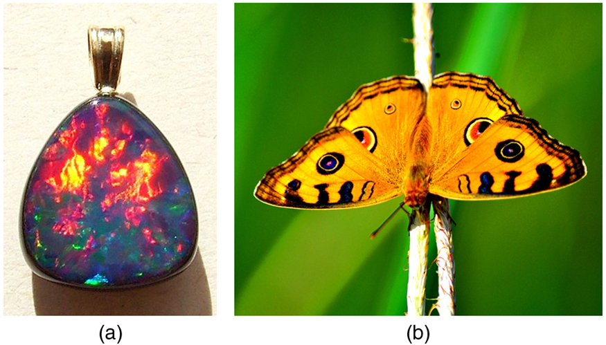
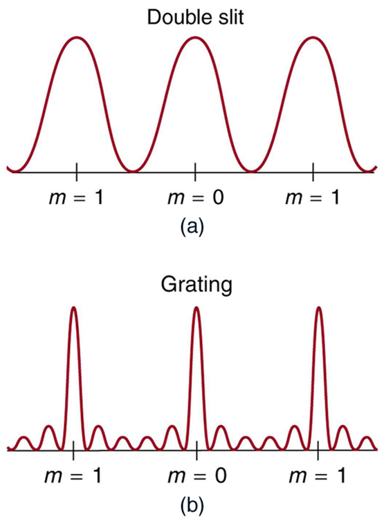
An interesting thing happens if you pass light through a large number of evenly spaced parallel slits, called a diffraction grating. An interference pattern is created that is very similar to the one formed by a double slit (see Figure 1). A diffraction grating can be manufactured by scratching glass with a sharp tool in a number of precisely positioned parallel lines, with the untouched regions acting like slits. These can be photographically mass produced rather cheaply. Diffraction gratings work both for transmission of light, as in Figure 1, and for reflection of light, as on butterfly wings and the Australian opal in Figure 2 or the CD pictured in the opening photograph of this chapter, Chapter 27 Figure 1. In addition to their use as novelty items, diffraction gratings are commonly used for spectroscopic dispersion and analysis of light. What makes them particularly useful is the fact that they form a sharper pattern than double slits do. That is, their bright regions are narrower and brighter, while their dark regions are darker. Figure 3 shows idealized graphs demonstrating the sharper pattern. Natural diffraction gratings occur in the feathers of certain birds. Tiny, finger-like structures in regular patterns act as reflection gratings, producing constructive interference that gives the feathers colors not solely due to their pigmentation. This is called iridescence.
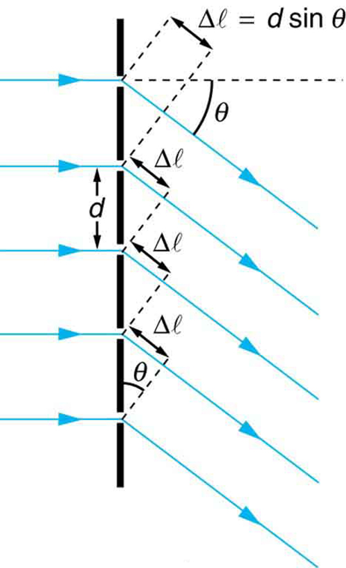
The analysis of a diffraction grating is very similar to that for a double slit (see Figure 4). As we know from our discussion of double slits in Chapter 27.3 Young’s Double Slit Experiment, light is diffracted by each slit and spreads out after passing through. Rays traveling in the same direction (at an angle [latex]{\theta}[/latex] relative to the incident direction) are shown in the figure. Each of these rays travels a different distance to a common point on a screen far away. The rays start in phase, and they can be in or out of phase when they reach a screen, depending on the difference in the path lengths traveled. As seen in the figure, each ray travels a distance [latex]{d \;\text{sin} \;\theta}[/latex] different from that of its neighbor, where [latex]{d}[/latex] is the distance between slits. If this distance equals an integral number of wavelengths, the rays all arrive in phase, and constructive interference (a maximum) is obtained. Thus, the condition necessary to obtain constructive interference for a diffraction grating is
where [latex]{d}[/latex] is the distance between slits in the grating, [latex]{\lambda}[/latex] is the wavelength of light, and [latex]{m}[/latex] is the order of the maximum. Note that this is exactly the same equation as for double slits separated by [latex]{d}[/latex]. However, the slits are usually closer in diffraction gratings than in double slits, producing fewer maxima at larger angles.
Where are diffraction gratings used? Diffraction gratings are key components of monochromators used, for example, in optical imaging of particular wavelengths from biological or medical samples. A diffraction grating can be chosen to specifically analyze a wavelength emitted by molecules in diseased cells in a biopsy sample or to help excite strategic molecules in the sample with a selected frequency of light. Another vital use is in optical fiber technologies where fibers are designed to provide optimum performance at specific wavelengths. A range of diffraction gratings are available for selecting specific wavelengths for such use.
Take-Home Experiment: Rainbows on a CD
The spacing [latex]{d}[/latex] of the grooves in a CD or DVD can be well determined by using a laser and the equation [latex]{d \;\text{sin} \;\text{sin} \; \theta = m \lambda , \text{for} \; m = \; 0, \; 1, \; -1, \; 2, \; -2, \; \dots}[/latex]. However, we can still make a good estimate of this spacing by using white light and the rainbow of colors that comes from the interference. Reflect sunlight from a CD onto a wall and use your best judgment of the location of a strongly diffracted color to find the separation [latex]{d}[/latex].
Example 1: Calculating Typical Diffraction Grating Effects
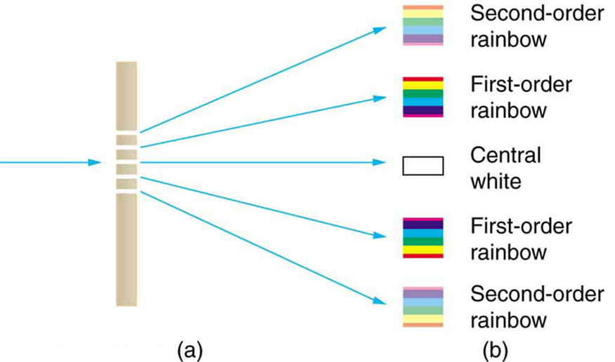
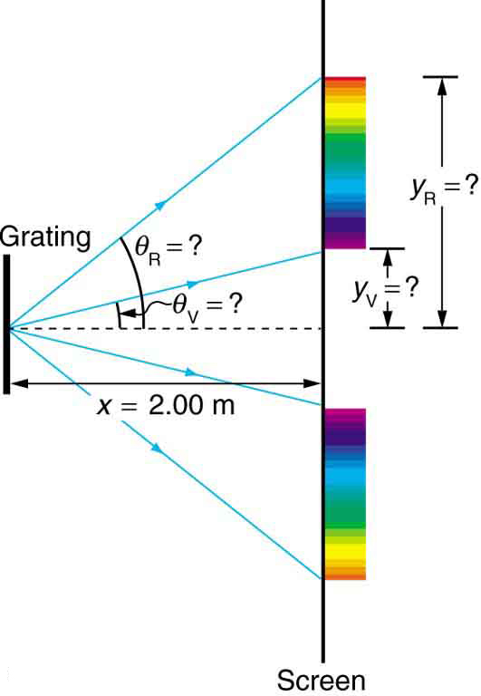
Diffraction gratings with 10,000 lines per centimeter are readily available. Suppose you have one, and you send a beam of white light through it to a screen 2.00 m away. (a) Find the angles for the first-order diffraction of the shortest and longest wavelengths of visible light (380 and 760 nm). (b) What is the distance between the ends of the rainbow of visible light produced on the screen for first-order interference? (See Figure 5.)
Strategy
The angles can be found using the equation
once a value for the slit spacing [latex]{d}[/latex] has been determined. Since there are 10,000 lines per centimeter, each line is separated by [latex]{1/10,000}[/latex] of a centimeter. Once the angles are found, the distances along the screen can be found using simple trigonometry.
Solution for (a)
The distance between slits is [latex]{d = (1 \;\text{cm})/10,000 = 1.00 \times 10^{-4} \;\text{cm or} 1.00 \times 10^{-6} \;\text{m}}[/latex]. Let us call the two angles [latex]{\theta _{\text{V}}}[/latex] for violet (380 nm) and [latex]{\theta _{\text{R}}}[/latex] for red (760 nm). Solving the equation [latex]{d \;\text{sin} \;\theta _{\text{V}} = m \lambda}[/latex] for [latex]{\text{sin} \;\theta _{\text{V}}}[/latex],
where [latex]{m = 1}[/latex] for first order and [latex]{\lambda _{\text{V}} = 380 \;\text{nm} = 3.80 \times 10^{-7} \;\text{m}}[/latex]. Substituting these values gives
Thus the angle [latex]{\theta _{\text{V}}}[/latex] is
Similarly,
Thus the angle [latex]{\theta _{\text{R}}}[/latex] is
Notice that in both equations, we reported the results of these intermediate calculations to four significant figures to use with the calculation in part (b).
Solution for (b)
The distances on the screen are labeled [latex]{y _{\text{V}}}[/latex] and [latex]{y _{\text{R}}}[/latex] in Figure 5. Noting that [latex]{\text{tan} \;\theta = y/x}[/latex], we can solve for [latex]{y _{\text{V}}}[/latex] and [latex]{y _{\text{R}}}[/latex]. That is,
and
The distance between them is therefore
Discussion
The large distance between the red and violet ends of the rainbow produced from the white light indicates the potential this diffraction grating has as a spectroscopic tool. The more it can spread out the wavelengths (greater dispersion), the more detail can be seen in a spectrum. This depends on the quality of the diffraction grating—it must be very precisely made in addition to having closely spaced lines.
Section Summary
- A diffraction grating is a large collection of evenly spaced parallel slits that produces an interference pattern similar to but sharper than that of a double slit.
- There is constructive interference for a diffraction grating when [latex]{d \;\text{sin} \; \theta = m \lambda , \; ( \text{for} \; m = 0, \; 1, \; -1, \; 2, \; -2 \; \dots)}[/latex], where [latex]{d}[/latex] is the distance between slits in the grating, [latex]{\lambda}[/latex] is the wavelength of light, and [latex]{m}[/latex] is the order of the maximum.
Conceptual Questions
1: What is the advantage of a diffraction grating over a double slit in dispersing light into a spectrum?
2: What are the advantages of a diffraction grating over a prism in dispersing light for spectral analysis?
3: Can the lines in a diffraction grating be too close together to be useful as a spectroscopic tool for visible light? If so, what type of EM radiation would the grating be suitable for? Explain.
4: If a beam of white light passes through a diffraction grating with vertical lines, the light is dispersed into rainbow colors on the right and left. If a glass prism disperses white light to the right into a rainbow, how does the sequence of colors compare with that produced on the right by a diffraction grating?
5: Suppose pure-wavelength light falls on a diffraction grating. What happens to the interference pattern if the same light falls on a grating that has more lines per centimeter? What happens to the interference pattern if a longer-wavelength light falls on the same grating? Explain how these two effects are consistent in terms of the relationship of wavelength to the distance between slits.
6: Suppose a feather appears green but has no green pigment. Explain in terms of diffraction.
7: It is possible that there is no minimum in the interference pattern of a single slit. Explain why. Is the same true of double slits and diffraction gratings?
Problems & Exercises
1: A diffraction grating has 2000 lines per centimeter. At what angle will the first-order maximum be for 520-nm-wavelength green light?
2: Find the angle for the third-order maximum for 580-nm-wavelength yellow light falling on a diffraction grating having 1500 lines per centimeter.
3: How many lines per centimeter are there on a diffraction grating that gives a first-order maximum for 470-nm blue light at an angle of [latex]{25.0 ^{\circ}}[/latex]?
4: What is the distance between lines on a diffraction grating that produces a second-order maximum for 760-nm red light at an angle of [latex]{60.0 ^{\circ}}[/latex]?
5: Calculate the wavelength of light that has its second-order maximum at [latex]{45.0 ^{\circ}}[/latex] when falling on a diffraction grating that has 5000 lines per centimeter.
6: An electric current through hydrogen gas produces several distinct wavelengths of visible light. What are the wavelengths of the hydrogen spectrum, if they form first-order maxima at angles of [latex]{24.2 ^{\circ}}[/latex], [latex]{25.7 ^{\circ}}[/latex], [latex]{29.1 ^{\circ}}[/latex], and [latex]{41.0 ^{\circ}}[/latex] when projected on a diffraction grating having 10,000 lines per centimeter? Explicitly show how you follow the steps in Chapter 27.7 Problem-Solving Strategies for Wave Optics
7: (a) What do the four angles in the above problem become if a 5000-line-per-centimeter diffraction grating is used? (b) Using this grating, what would the angles be for the second-order maxima? (c) Discuss the relationship between integral reductions in lines per centimeter and the new angles of various order maxima.
8: What is the maximum number of lines per centimeter a diffraction grating can have and produce a complete first-order spectrum for visible light?
9: The yellow light from a sodium vapor lamp seems to be of pure wavelength, but it produces two first-order maxima at [latex]{36.093 ^{\circ}}[/latex] and [latex]{36.129 ^{\circ}}[/latex] when projected on a 10,000 line per centimeter diffraction grating. What are the two wavelengths to an accuracy of 0.1 nm?
10: What is the spacing between structures in a feather that acts as a reflection grating, given that they produce a first-order maximum for 525-nm light at a [latex]{30.0 ^{\circ}}[/latex] angle?
11: Structures on a bird feather act like a reflection grating having 8000 lines per centimeter. What is the angle of the first-order maximum for 600-nm light?
12: An opal such as that shown in Figure 2 acts like a reflection grating with rows separated by about [latex]{8 \;\mu \text{m}}[/latex]. If the opal is illuminated normally, (a) at what angle will red light be seen and (b) at what angle will blue light be seen?
13: At what angle does a diffraction grating produces a second-order maximum for light having a first-order maximum at [latex]{20.0 ^{\circ}}[/latex]?
14: Show that a diffraction grating cannot produce a second-order maximum for a given wavelength of light unless the first-order maximum is at an angle less than [latex]{30.0 ^{\circ}}[/latex].
15: If a diffraction grating produces a first-order maximum for the shortest wavelength of visible light at [latex]{30.0 ^{\circ}}[/latex], at what angle will the first-order maximum be for the longest wavelength of visible light?
16: (a) Find the maximum number of lines per centimeter a diffraction grating can have and produce a maximum for the smallest wavelength of visible light. (b) Would such a grating be useful for ultraviolet spectra? (c) For infrared spectra?
17: (a) Show that a 30,000-line-per-centimeter grating will not produce a maximum for visible light. (b) What is the longest wavelength for which it does produce a first-order maximum? (c) What is the greatest number of lines per centimeter a diffraction grating can have and produce a complete second-order spectrum for visible light?
18: A He–Ne laser beam is reflected from the surface of a CD onto a wall. The brightest spot is the reflected beam at an angle equal to the angle of incidence. However, fringes are also observed. If the wall is 1.50 m from the CD, and the first fringe is 0.600 m from the central maximum, what is the spacing of grooves on the CD?
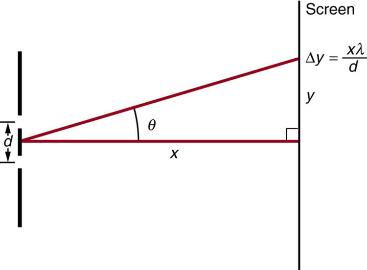
19: The analysis shown in the figure below also applies to diffraction gratings with lines separated by a distance [latex]{d}[/latex]. What is the distance between fringes produced by a diffraction grating having 125 lines per centimeter for 600-nm light, if the screen is 1.50 m away?
20: Unreasonable Results
Red light of wavelength of 700 nm falls on a double slit separated by 400 nm. (a) At what angle is the first-order maximum in the diffraction pattern? (b) What is unreasonable about this result? (c) Which assumptions are unreasonable or inconsistent?
21: Unreasonable Results
(a) What visible wavelength has its fourth-order maximum at an angle of [latex]{25.0 ^{\circ}}[/latex] when projected on a 25,000-line-per-centimeter diffraction grating? (b) What is unreasonable about this result? (c) Which assumptions are unreasonable or inconsistent?
22: Construct Your Own Problem
Consider a spectrometer based on a diffraction grating. Construct a problem in which you calculate the distance between two wavelengths of electromagnetic radiation in your spectrometer. Among the things to be considered are the wavelengths you wish to be able to distinguish, the number of lines per meter on the diffraction grating, and the distance from the grating to the screen or detector. Discuss the practicality of the device in terms of being able to discern between wavelengths of interest.
Glossary
- constructive interference for a diffraction grating
- occurs when the condition [latex]{d \;\text{sin} \; \theta = m \lambda (\text{for} \; m = \; 0, \; 1, \; -1, \; 2, \; -2, \; \dots)}[/latex] is satisfied, where [latex]{d}[/latex] is the distance between slits in the grating, [latex]{\lambda}[/latex] is the wavelength of light, and [latex]{m}[/latex] is the order of the maximum
- diffraction grating
- a large number of evenly spaced parallel slits
Solutions
Problems & Exercises
1: [latex]{5.97 ^{\circ}}[/latex]
3: [latex]{8.99 \times 10^3}[/latex]
5: 707 nm
7: (a) [latex]{11.8^{\circ}, \; 12.5^{\circ}, \; 14.1^{\circ}, \; 19.2^{\circ}}[/latex]
(b) [latex]{24.2^{\circ} , \; 25.7^{\circ}, \; 29.1^{\circ}, \; 41.0^{\circ}}[/latex]
(c) Decreasing the number of lines per centimeter by a factor of x means that the angle for the x-order maximum is the same as the original angle for the first – order maximum.
9: 589.1 nm and 589.6 nm
11: [latex]{28.7 ^{\circ}}[/latex]
13: [latex]{43.2 ^{\circ}}[/latex]
15: [latex]{90.0 ^{\circ}}[/latex]
17: (a) The longest wavelength is 333.3 nm, which is not visible.
(b) 333 nm (UV)
(c) [latex]{6.58 \times 10^3 \;\text{cm}}[/latex]
19: [latex]{1.13 \times 10^{-2} \;\text{m}}[/latex]
(a) 42.3 nm
(b) Not a visible wavelength
The number of slits in this diffraction grating is too large. Etching in integrated circuits can be done to a resolution of 50 nm, so slit separations of 400 nm are at the limit of what we can do today. This line spacing is too small to produce diffraction of light.
