
Chapter 25 Geometric Optics
25.7 Image Formation by Mirrors
Summary
- Illustrate image formation in a flat mirror.
- Explain with ray diagrams the formation of an image using spherical mirrors.
- Determine focal length and magnification given radius of curvature, distance of object and image.
We only have to look as far as the nearest bathroom to find an example of an image formed by a mirror. Images in flat mirrors are the same size as the object and are located behind the mirror. Like lenses, mirrors can form a variety of images. For example, dental mirrors may produce a magnified image, just as makeup mirrors do. Security mirrors in shops, on the other hand, form images that are smaller than the object. We will use the law of reflection to understand how mirrors form images, and we will find that mirror images are analogous to those formed by lenses.
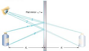
Figure 1 helps illustrate how a flat mirror forms an image. Two rays are shown emerging from the same point, striking the mirror, and being reflected into the observer’s eye. The rays can diverge slightly, and both still get into the eye. If the rays are extrapolated backward, they seem to originate from a common point behind the mirror, locating the image. (The paths of the reflected rays into the eye are the same as if they had come directly from that point behind the mirror.) Using the law of reflection—the angle of reflection equals the angle of incidence—we can see that the image and object are the same distance from the mirror. This is a virtual image, since it cannot be projected—the rays only appear to originate from a common point behind the mirror. Obviously, if you walk behind the mirror, you cannot see the image, since the rays do not go there. But in front of the mirror, the rays behave exactly as if they had come from behind the mirror, so that is where the image is situated.
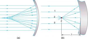
Now let us consider the focal length of a mirror—for example, the concave spherical mirrors in Figure 2. Rays of light that strike the surface follow the law of reflection. For a mirror that is large compared with its radius of curvature, as in Figure 2(a), we see that the reflected rays do not cross at the same point, and the mirror does not have a well-defined focal point. If the mirror had the shape of a parabola, the rays would all cross at a single point, and the mirror would have a well-defined focal point. But parabolic mirrors are much more expensive to make than spherical mirrors. The solution is to use a mirror that is small compared with its radius of curvature, as shown in Figure 2(b). (This is the mirror equivalent of the thin lens approximation.) To a very good approximation, this mirror has a well-defined focal point at F that is the focal distance [latex]{f}[/latex] from the center of the mirror. The focal length [latex]{f}[/latex] of a concave mirror is positive, since it is a converging mirror.
Just as for lenses, the shorter the focal length, the more powerful the mirror; thus, [latex]{P = 1/f}[/latex] for a mirror, too. A more strongly curved mirror has a shorter focal length and a greater power. Using the law of reflection and some simple trigonometry, it can be shown that the focal length is half the radius of curvature, or
where [latex]{R}[/latex] is the radius of curvature of a spherical mirror. The smaller the radius of curvature, the smaller the focal length and, thus, the more powerful the mirror.
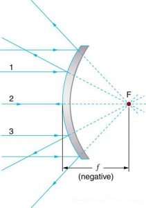
The convex mirror shown in Figure 3 also has a focal point. Parallel rays of light reflected from the mirror seem to originate from the point F at the focal distance [latex]{f}[/latex] behind the mirror. The focal length and power of a convex mirror are negative, since it is a diverging mirror.
Ray tracing is as useful for mirrors as for lenses. The rules for ray tracing for mirrors are based on the illustrations just discussed:
- A ray approaching a concave converging mirror parallel to its axis is reflected through the focal point F of the mirror on the same side. (See rays 1 and 3 in Figure 2(b).)
- A ray approaching a convex diverging mirror parallel to its axis is reflected so that it seems to come from the focal point F behind the mirror. (See rays 1 and 3 in Figure 3.)
- Any ray striking the center of a mirror is followed by applying the law of reflection; it makes the same angle with the axis when leaving as when approaching. (See ray 2 in Figure 4.)
- A ray approaching a concave converging mirror through its focal point is reflected parallel to its axis. (The reverse of rays 1 and 3 in Figure 2.)
- A ray approaching a convex diverging mirror by heading toward its focal point on the opposite side is reflected parallel to the axis. (The reverse of rays 1 and 3 in Figure 3.)
We will use ray tracing to illustrate how images are formed by mirrors, and we can use ray tracing quantitatively to obtain numerical information. But since we assume each mirror is small compared with its radius of curvature, we can use the thin lens equations for mirrors just as we did for lenses.
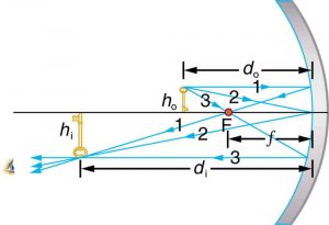
Consider the situation shown in Figure 4, concave spherical mirror reflection, in which an object is placed farther from a concave (converging) mirror than its focal length. That is, [latex]{f}[/latex] is positive and [latex]{d_o > f}[/latex], so that we may expect an image similar to the case 1 real image formed by a converging lens. Ray tracing in Figure 4 shows that the rays from a common point on the object all cross at a point on the same side of the mirror as the object. Thus a real image can be projected onto a screen placed at this location. The image distance is positive, and the image is inverted, so its magnification is negative. This is a case 1 image for mirrors. It differs from the case 1 image for lenses only in that the image is on the same side of the mirror as the object. It is otherwise identical.
Example 1: A Concave Reflector
Electric room heaters use a concave mirror to reflect infrared (IR) radiation from hot coils. Note that IR follows the same law of reflection as visible light. Given that the mirror has a radius of curvature of 50.0 cm and produces an image of the coils 3.00 m away from the mirror, where are the coils?
Strategy and Concept
We are given that the concave mirror projects a real image of the coils at an image distance [latex]{d_i = 3.00 \;\text{m}}[/latex]. The coils are the object, and we are asked to find their location—that is, to find the object distance dodo. We are also given the radius of curvature of the mirror, so that its focal length is [latex]{f = R/2 = 25.0 \;\text{cm}}[/latex] (positive since the mirror is concave or converging). Assuming the mirror is small compared with its radius of curvature, we can use the thin lens equations, to solve this problem.
Solution
Since [latex]{d_{\text{i}}}[/latex] and [latex]{f}[/latex] are known, thin lens equation can be used to find [latex]{d_{\text{o}}}[/latex]:
Rearranging to isolate [latex]{d_{\text{o}}}[/latex] gives
Entering known quantities gives a value for [latex]{1/d_{\text{o}}}[/latex]:
This must be inverted to find [latex]{d_{\text{o}}}[/latex]:
Discussion
Note that the object (the filament) is farther from the mirror than the mirror’s focal length. This is a case 1 image ([latex]{d_{\text{o}} > f}[/latex] and [latex]{f}[/latex] positive), consistent with the fact that a real image is formed. You will get the most concentrated thermal energy directly in front of the mirror and 3.00 m away from it. Generally, this is not desirable, since it could cause burns. Usually, you want the rays to emerge parallel, and this is accomplished by having the filament at the focal point of the mirror.
Note that the filament here is not much farther from the mirror than its focal length and that the image produced is considerably farther away. This is exactly analogous to a slide projector. Placing a slide only slightly farther away from the projector lens than its focal length produces an image significantly farther away. As the object gets closer to the focal distance, the image gets farther away. In fact, as the object distance approaches the focal length, the image distance approaches infinity and the rays are sent out parallel to one another.
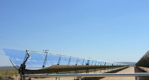
Example 2: Solar Electric Generating System
One of the solar technologies used today for generating electricity is a device (called a parabolic trough or concentrating collector) that concentrates the sunlight onto a blackened pipe that contains a fluid. This heated fluid is pumped to a heat exchanger, where its heat energy is transferred to another system that is used to generate steam—and so generate electricity through a conventional steam cycle. Figure 5 shows such a working system in southern California. Concave mirrors are used to concentrate the sunlight onto the pipe. The mirror has the approximate shape of a section of a cylinder. For the problem, assume that the mirror is exactly one-quarter of a full cylinder.
- If we wish to place the fluid-carrying pipe 40.0 cm from the concave mirror at the mirror’s focal point, what will be the radius of curvature of the mirror?
- Per meter of pipe, what will be the amount of sunlight concentrated onto the pipe, assuming the insolation (incident solar radiation) is [latex]{0.900 \;\text{kW/m}^2}[/latex]?
- If the fluid-carrying pipe has a 2.00-cm diameter, what will be the temperature increase of the fluid per meter of pipe over a period of one minute? Assume all the solar radiation incident on the reflector is absorbed by the pipe, and that the fluid is mineral oil.
Strategy
To solve an Integrated Concept Problem we must first identify the physical principles involved. Part (a) is related to the current topic. Part (b) involves a little math, primarily geometry. Part (c) requires an understanding of heat and density.
Solution to (a)
To a good approximation for a concave or semi-spherical surface, the point where the parallel rays from the sun converge will be at the focal point, so [latex]{R = 2f =80.0 \;\text{cm}}[/latex].
Solution to (b)
The insolation is [latex]{900 \;\text{W/m}^2}[/latex]. We must find the cross-sectional area [latex]\text{A}[/latex] of the concave mirror, since the power delivered is [latex]{900 \;\text{W/m}^2 \times \;\text{A}}[/latex]. The mirror in this case is a quarter-section of a cylinder, so the area for a length [latex]\text{L}[/latex] of the mirror is [latex]{\text{A} = \frac{1}{4}(2 \pi R) \text{L}}[/latex]. The area for a length of 1.00 m is then
The insolation on the 1.00-m length of pipe is then
Solution to (c)
The increase in temperature is given by [latex]{Q = mc \Delta T}[/latex]. The mass [latex]{m}[/latex] of the mineral oil in the one-meter section of pipe is
Therefore, the increase in temperature in one minute is
Discussion for (c)
An array of such pipes in the California desert can provide a thermal output of 250 MW on a sunny day, with fluids reaching temperatures as high as [latex]{400 ^{\circ} \text{C}}[/latex]. We are considering only one meter of pipe here, and ignoring heat losses along the pipe.
What happens if an object is closer to a concave mirror than its focal length? This is analogous to a case 2 image for lenses ([latex]{d_{\text{o}} f}[/latex] and [latex]{f}[/latex] positive), which is a magnifier. In fact, this is how makeup mirrors act as magnifiers. Figure 6(a) uses ray tracing to locate the image of an object placed close to a concave mirror. Rays from a common point on the object are reflected in such a manner that they appear to be coming from behind the mirror, meaning that the image is virtual and cannot be projected. As with a magnifying glass, the image is upright and larger than the object. This is a case 2 image for mirrors and is exactly analogous to that for lenses.
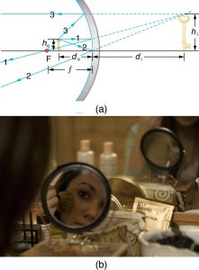
All three rays appear to originate from the same point after being reflected, locating the upright virtual image behind the mirror and showing it to be larger than the object. (b) Makeup mirrors are perhaps the most common use of a concave mirror to produce a larger, upright image.
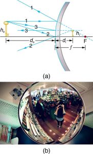
A convex mirror is a diverging mirror ([latex]{f}[/latex] is negative) and forms only one type of image. It is a case 3 image—one that is upright and smaller than the object, just as for diverging lenses. Figure 7(a) uses ray tracing to illustrate the location and size of the case 3 image for mirrors. Since the image is behind the mirror, it cannot be projected and is thus a virtual image. It is also seen to be smaller than the object.
Example 3: Image in a Convex Mirror
A keratometer is a device used to measure the curvature of the cornea, particularly for fitting contact lenses. Light is reflected from the cornea, which acts like a convex mirror, and the keratometer measures the magnification of the image. The smaller the magnification, the smaller the radius of curvature of the cornea. If the light source is 12.0 cm from the cornea and the image’s magnification is 0.0320, what is the cornea’s radius of curvature?
Strategy
If we can find the focal length of the convex mirror formed by the cornea, we can find its radius of curvature (the radius of curvature is twice the focal length of a spherical mirror). We are given that the object distance is [latex]{d_o = 12.0 \;\text{cm}}[/latex] and that [latex]{m = 0.0320}[/latex]. We first solve for the image distance [latex]{d_i}[/latex], and then for [latex]{f}[/latex].
Solution
[latex]{m = -d_{\text{i}} / d_{\text{o}}}[/latex]. Solving this expression for didi gives
Entering known values yields
Substituting known values,
This must be inverted to find [latex]{f}[/latex]:
The radius of curvature is twice the focal length, so that
Discussion
Although the focal length [latex]{f}[/latex] of a convex mirror is defined to be negative, we take the absolute value to give us a positive value for [latex]{R}[/latex]. The radius of curvature found here is reasonable for a cornea. The distance from cornea to retina in an adult eye is about 2.0 cm. In practice, many corneas are not spherical, complicating the job of fitting contact lenses. Note that the image distance here is negative, consistent with the fact that the image is behind the mirror, where it cannot be projected. In this section’s Problems and Exercises, you will show that for a fixed object distance, the smaller the radius of curvature, the smaller the magnification.
The three types of images formed by mirrors (cases 1, 2, and 3) are exactly analogous to those formed by lenses, as summarized in the table at the end of Chapter 25.6 Image Formation by Lenses. It is easiest to concentrate on only three types of images—then remember that concave mirrors act like convex lenses, whereas convex mirrors act like concave lenses.
Take-Home Experiment: Concave Mirrors Close to Home
Find a flashlight and identify the curved mirror used in it. Find another flashlight and shine the first flashlight onto the second one, which is turned off. Estimate the focal length of the mirror. You might try shining a flashlight on the curved mirror behind the headlight of a car, keeping the headlight switched off, and determine its focal length.
Problem-Solving Strategy for Mirrors
Step 1. Examine the situation to determine that image formation by a mirror is involved.
Step 2. Refer to the Problem-Solving Strategies for Lenses. The same strategies are valid for mirrors as for lenses with one qualification—use the ray tracing rules for mirrors listed earlier in this section.
Section Summary
- The characteristics of an image formed by a flat mirror are: (a) The image and object are the same distance from the mirror, (b) The image is a virtual image, and (c) The image is situated behind the mirror.
- Image length is half the radius of curvature.
[latex]{f =}[/latex] [latex]{\frac{R}{2}}[/latex]
- A convex mirror is a diverging mirror and forms only one type of image, namely a virtual image.
Conceptual Questions
1: What are the differences between real and virtual images? How can you tell (by looking) whether an image formed by a single lens or mirror is real or virtual?
2: Can you see a virtual image? Can you photograph one? Can one be projected onto a screen with additional lenses or mirrors? Explain your responses.
3: Is it necessary to project a real image onto a screen for it to exist?
4: At what distance is an image always located—at [latex]{d_{\text{o}}}[/latex], [latex]{d_{\text{i}}}[/latex], or [latex]{f}[/latex]?
5: Under what circumstances will an image be located at the focal point of a lens or mirror?
6: What is meant by a negative magnification? What is meant by a magnification that is less than 1 in magnitude?
7: Can a case 1 image be larger than the object even though its magnification is always negative? Explain.
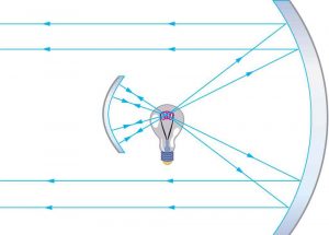
8: Figure 8 shows a light bulb between two mirrors. One mirror produces a beam of light with parallel rays; the other keeps light from escaping without being put into the beam. Where is the filament of the light in relation to the focal point or radius of curvature of each mirror?
9: Devise an arrangement of mirrors allowing you to see the back of your head. What is the minimum number of mirrors needed for this task?
10: If you wish to see your entire body in a flat mirror (from head to toe), how tall should the mirror be? Does its size depend upon your distance away from the mirror? Provide a sketch.
11: It can be argued that a flat mirror has an infinite focal length. If so, where does it form an image? That is, how are [latex]{d_{\text{i}}}[/latex] and [latex]{d_{\text{o}}}[/latex] related?
12: Why are diverging mirrors often used for rear-view mirrors in vehicles? What is the main disadvantage of using such a mirror compared with a flat one?
Problems & Exercises
1: What is the focal length of a makeup mirror that has a power of 1.50 D?
2: Some telephoto cameras use a mirror rather than a lens. What radius of curvature mirror is needed to replace a 800 mm focal length telephoto lens?
3: (a) Calculate the focal length of the mirror formed by the shiny back of a spoon that has a 3.00 cm radius of curvature. (b) What is its power in diopters?
4: Find the magnification of the heater element in Example 1. Note that its large magnitude helps spread out the reflected energy.
5: What is the focal length of a makeup mirror that produces a magnification of 1.50 when a person’s face is 12.0 cm away? Explicitly show how you follow the steps in the Problem-Solving Strategy for Mirrors.
6: A shopper standing 3.00 m from a convex security mirror sees his image with a magnification of 0.250. (a) Where is his image? (b) What is the focal length of the mirror? (c) What is its radius of curvature? Explicitly show how you follow the steps in the Problem-Solving Strategy for Mirrors.
7: An object 1.50 cm high is held 3.00 cm from a person’s cornea, and its reflected image is measured to be 0.167 cm high. (a) What is the magnification? (b) Where is the image? (c) Find the radius of curvature of the convex mirror formed by the cornea. (Note that this technique is used by optometrists to measure the curvature of the cornea for contact lens fitting. The instrument used is called a keratometer, or curve measurer.)
8: Ray tracing for a flat mirror shows that the image is located a distance behind the mirror equal to the distance of the object from the mirror. This is stated [latex]{d_{\text{i}} = -d_{\text{o}}}[/latex], since this is a negative image distance (it is a virtual image). (a) What is the focal length of a flat mirror? (b) What is its power?
9: Show that for a flat mirror [latex]{h_{\text{i}} = h_{\text{o}}}[/latex], knowing that the image is a distance behind the mirror equal in magnitude to the distance of the object from the mirror.
10: Use the law of reflection to prove that the focal length of a mirror is half its radius of curvature. That is, prove that [latex]{f = R/2}[/latex]. Note this is true for a spherical mirror only if its diameter is small compared with its radius of curvature.
11: Referring to the electric room heater considered in the first example in this section, calculate the intensity of IR radiation in [latex]{\text{W/m}^2}[/latex] projected by the concave mirror on a person 3.00 m away. Assume that the heating element radiates 1500 W and has an area of [latex]{100 \;\text{cm}^2}[/latex], and that half of the radiated power is reflected and focused by the mirror.
12: Consider a 250-W heat lamp fixed to the ceiling in a bathroom. If the filament in one light burns out then the remaining three still work. Construct a problem in which you determine the resistance of each filament in order to obtain a certain intensity projected on the bathroom floor. The ceiling is 3.0 m high. The problem will need to involve concave mirrors behind the filaments. Your instructor may wish to guide you on the level of complexity to consider in the electrical components.
Glossary
- converging mirror
- a concave mirror in which light rays that strike it parallel to its axis converge at one or more points along the axis
- diverging mirror
- a convex mirror in which light rays that strike it parallel to its axis bend away (diverge) from its axis
- law of reflection
- angle of reflection equals the angle of incidence
Solutions
Problems & Exercises
1: +0.667 m
3: (a) [latex]{-1.5 \times 10^{-2} \;\text{m}}[/latex]
(b) [latex]{-66.7 \;\text{D}}[/latex]
5: +0.360 m (concave)
7: (a) +0.111
(b) -0.334 cm (behind “mirror”)
(c) 0.752cm
11: [latex]{6.82 \;\text{kW/m}^2}[/latex]
