
Chapter 27 Wave Optics
27.8 Polarization
Summary
- Discuss the meaning of polarization.
- Discuss the property of optical activity of certain materials.
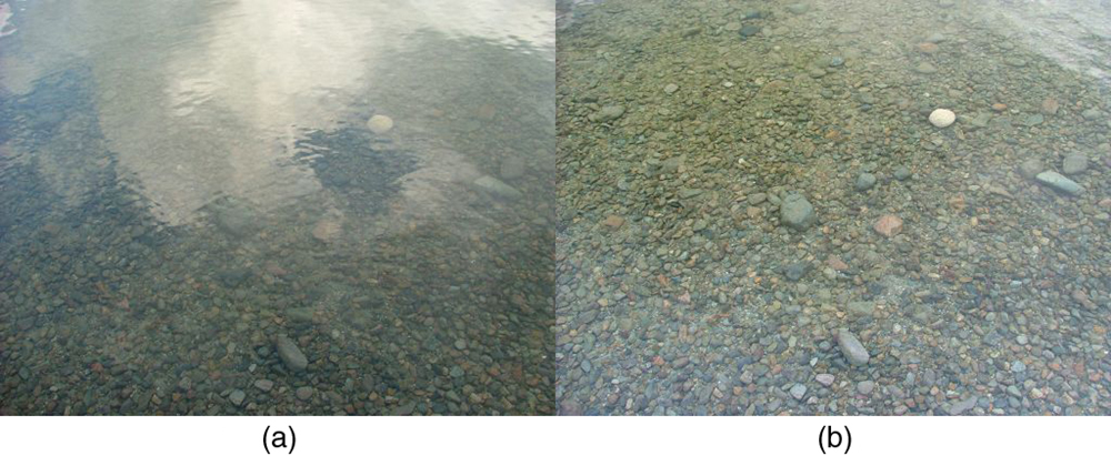
Polaroid sunglasses are familiar to most of us. They have a special ability to cut the glare of light reflected from water or glass (see Figure 1). Polaroids have this ability because of a wave characteristic of light called polarization. What is polarization? How is it produced? What are some of its uses? The answers to these questions are related to the wave character of light.
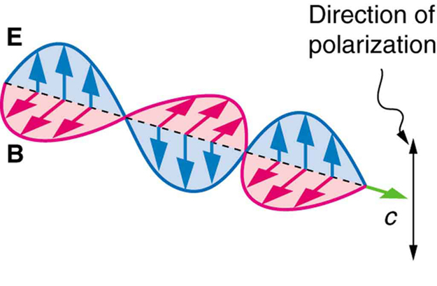
Light is one type of electromagnetic (EM) wave. As noted earlier, EM waves are transverse waves consisting of varying electric and magnetic fields that oscillate perpendicular to the direction of propagation (see Figure 2). There are specific directions for the oscillations of the electric and magnetic fields. Polarization is the attribute that a wave’s oscillations have a definite direction relative to the direction of propagation of the wave. (This is not the same type of polarization as that discussed for the separation of charges.) Waves having such a direction are said to be polarized. For an EM wave, we define the direction of polarization to be the direction parallel to the electric field. Thus we can think of the electric field arrows as showing the direction of polarization, as in Figure 2.
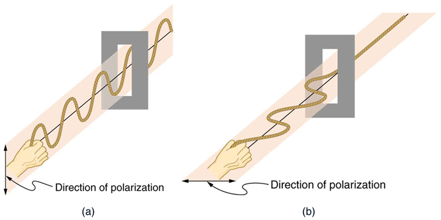
To examine this further, consider the transverse waves in the ropes shown in Figure 3. The oscillations in one rope are in a vertical plane and are said to be vertically polarized. Those in the other rope are in a horizontal plane and are horizontally polarized. If a vertical slit is placed on the first rope, the waves pass through. However, a vertical slit blocks the horizontally polarized waves. For EM waves, the direction of the electric field is analogous to the disturbances on the ropes.
The Sun and many other light sources produce waves that are randomly polarized (see Figure 4). Such light is said to be unpolarized because it is composed of many waves with all possible directions of polarization. Polaroid materials, invented by the founder of Polaroid Corporation, Edwin Land, act as a polarizing slit for light, allowing only polarization in one direction to pass through. Polarizing filters are composed of long molecules aligned in one direction. Thinking of the molecules as many slits, analogous to those for the oscillating ropes, we can understand why only light with a specific polarization can get through. The axis of a polarizing filter is the direction along which the filter passes the electric field of an EM wave (see Figure 5).
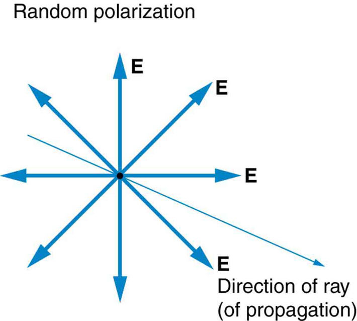
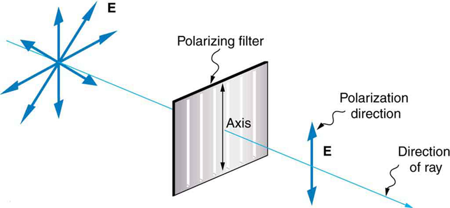
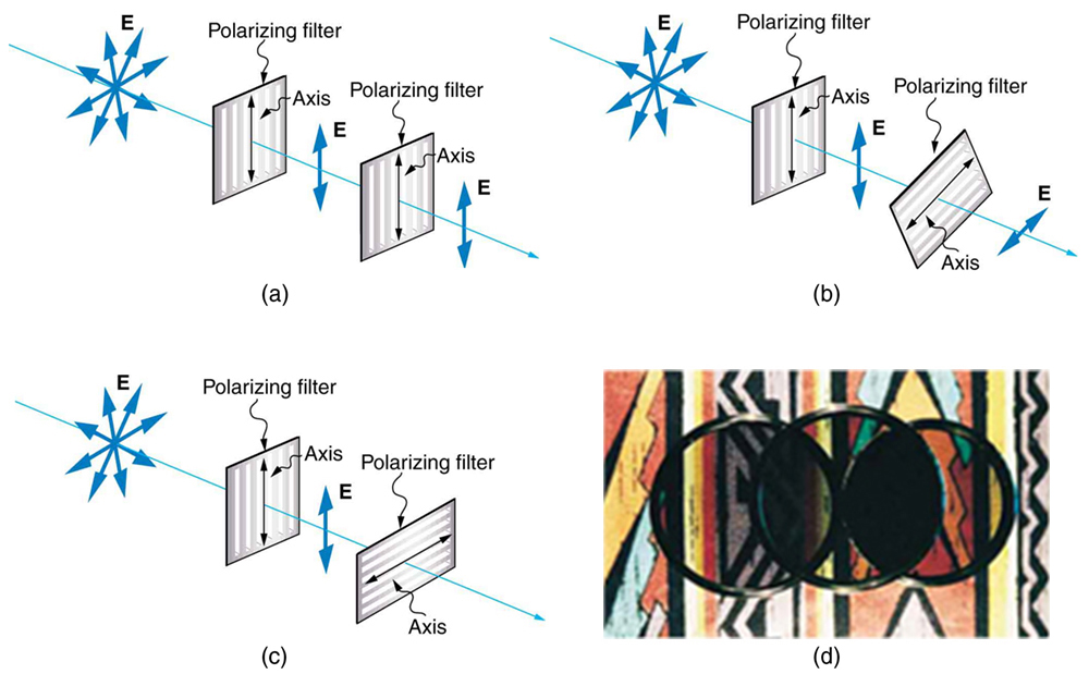
Figure 6 shows the effect of two polarizing filters on originally unpolarized light. The first filter polarizes the light along its axis. When the axes of the first and second filters are aligned (parallel), then all of the polarized light passed by the first filter is also passed by the second. If the second polarizing filter is rotated, only the component of the light parallel to the second filter’s axis is passed. When the axes are perpendicular, no light is passed by the second.
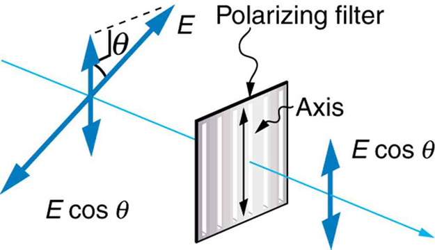
Only the component of the EM wave parallel to the axis of a filter is passed. Let us call the angle between the direction of polarization and the axis of a filter [latex]{\theta}[/latex]. If the electric field has an amplitude [latex]{E}[/latex], then the transmitted part of the wave has an amplitude [latex]{E \;\text{cos} \; \theta}[/latex] (see Figure 7). Since the intensity of a wave is proportional to its amplitude squared, the intensity [latex]{I}[/latex] of the transmitted wave is related to the incident wave by
where [latex]{I_0}[/latex] is the intensity of the polarized wave before passing through the filter. (The above equation is known as Malus’s law.)
Example 1: Calculating Intensity Reduction by a Polarizing Filter
What angle is needed between the direction of polarized light and the axis of a polarizing filter to reduce its intensity by [latex]{90.0 \%}[/latex]?
Strategy
When the intensity is reduced by [latex]{90.0 \%}[/latex], it is [latex]{10.0 \%}[/latex] or 0.100 times its original value. That is, [latex]{I = 0.100 I_0}[/latex]. Using this information, the equation [latex]{I = I_0 \;\text{cos}^2 \;\theta}[/latex] can be used to solve for the needed angle.
Solution
Solving the equation [latex]{I = I_0 \;\text{cos}^2 \;\theta}[/latex] for [latex]{\text{cos} \;\theta}[/latex] and substituting with the relationship between [latex]{I}[/latex] and [latex]{I_0}[/latex] gives
Solving for [latex]{\theta}[/latex] yields
Discussion
A fairly large angle between the direction of polarization and the filter axis is needed to reduce the intensity to [latex]{10.0 \%}[/latex] of its original value. This seems reasonable based on experimenting with polarizing films. It is interesting that, at an angle of [latex]{45^{\circ}}[/latex], the intensity is reduced to [latex]{50 \%}[/latex] of its original value (as you will show in this section’s Problems & Exercises). Note that [latex]{71.6 ^{\circ}}[/latex] is [latex]{18.4^{\circ}}[/latex] from reducing the intensity to zero, and that at an angle of [latex]{18.4 ^{\circ}}[/latex] the intensity is reduced to [latex]{90.0 \%}[/latex] of its original value (as you will also show in Problems & Exercises), giving evidence of symmetry.
Polarization by Reflection
By now you can probably guess that Polaroid sunglasses cut the glare in reflected light because that light is polarized. You can check this for yourself by holding Polaroid sunglasses in front of you and rotating them while looking at light reflected from water or glass. As you rotate the sunglasses, you will notice the light gets bright and dim, but not completely black. This implies the reflected light is partially polarized and cannot be completely blocked by a polarizing filter.
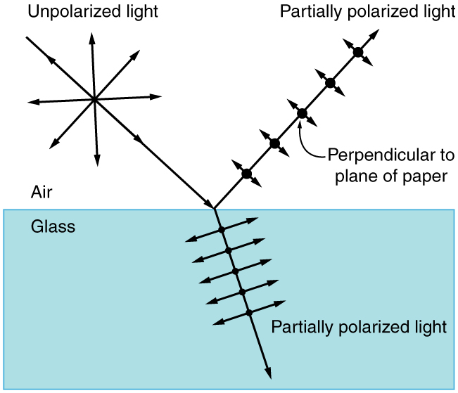
Figure 8 illustrates what happens when unpolarized light is reflected from a surface. Vertically polarized light is preferentially refracted at the surface, so that the reflected light is left more horizontally polarized. The reasons for this phenomenon are beyond the scope of this text, but a convenient mnemonic for remembering this is to imagine the polarization direction to be like an arrow. Vertical polarization would be like an arrow perpendicular to the surface and would be more likely to stick and not be reflected. Horizontal polarization is like an arrow bouncing on its side and would be more likely to be reflected. Sunglasses with vertical axes would then block more reflected light than unpolarized light from other sources.
Since the part of the light that is not reflected is refracted, the amount of polarization depends on the indices of refraction of the media involved. It can be shown that reflected light is completely polarized at a angle of reflection [latex]{\theta _{\text{b}}}[/latex], given by
where [latex]{n_1}[/latex] is the medium in which the incident and reflected light travel and [latex]{n_2}[/latex] is the index of refraction of the medium that forms the interface that reflects the light. This equation is known as Brewster’s law, and [latex]{\theta _{\text{b}}}[/latex] is known as Brewster’s angle, named after the 19th-century Scottish physicist who discovered them.
Things Great and Small: Atomic Explanation of Polarizing Filters
Polarizing filters have a polarization axis that acts as a slit. This slit passes electromagnetic waves (often visible light) that have an electric field parallel to the axis. This is accomplished with long molecules aligned perpendicular to the axis as shown in Figure 9.
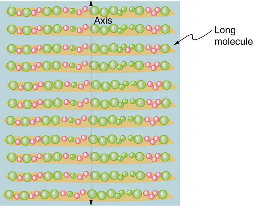
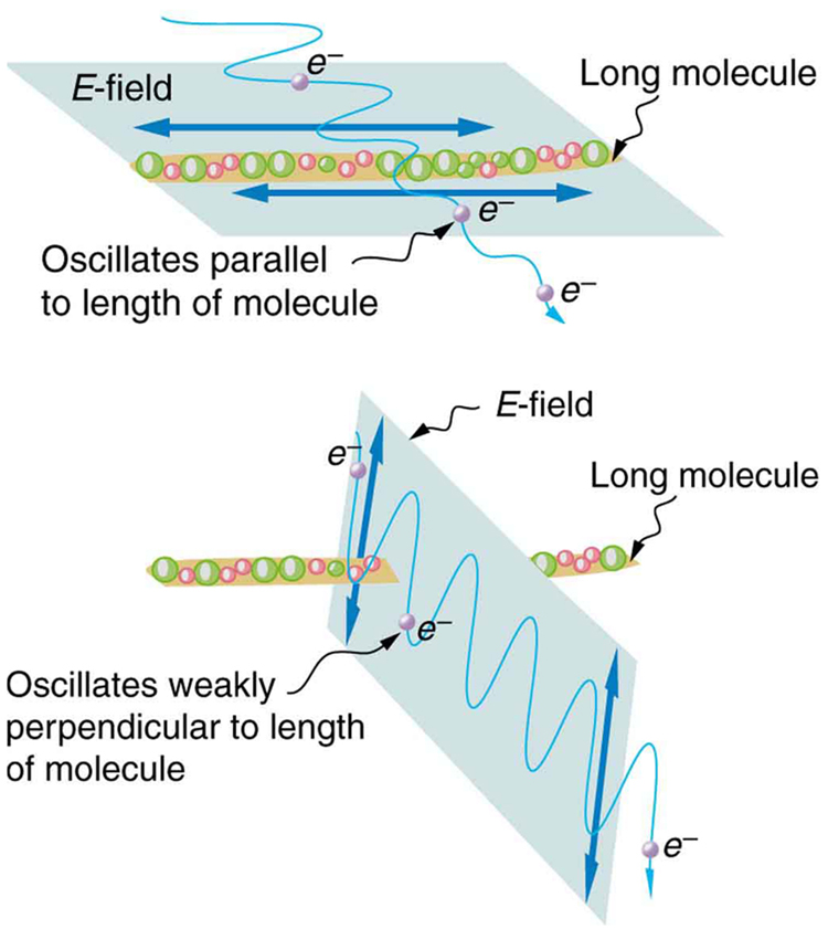
Figure 10 illustrates how the component of the electric field parallel to the long molecules is absorbed. An electromagnetic wave is composed of oscillating electric and magnetic fields. The electric field is strong compared with the magnetic field and is more effective in exerting force on charges in the molecules. The most affected charged particles are the electrons in the molecules, since electron masses are small. If the electron is forced to oscillate, it can absorb energy from the EM wave. This reduces the fields in the wave and, hence, reduces its intensity. In long molecules, electrons can more easily oscillate parallel to the molecule than in the perpendicular direction. The electrons are bound to the molecule and are more restricted in their movement perpendicular to the molecule. Thus, the electrons can absorb EM waves that have a component of their electric field parallel to the molecule. The electrons are much less responsive to electric fields perpendicular to the molecule and will allow those fields to pass. Thus the axis of the polarizing filter is perpendicular to the length of the molecule.
Example 2: Calculating Polarization by Reflection
(a) At what angle will light traveling in air be completely polarized horizontally when reflected from water? (b) From glass?
Strategy
All we need to solve these problems are the indices of refraction. Air has [latex]{n_1 = 1.00}[/latex], water has [latex]{n_2 = 1.333}[/latex], and crown glass has [latex]{{n^{\prime}}_2 = 1.520}[/latex]. The equation [latex]{\text{tan} \;\theta_{\text{b}} = \frac{n_2}{n_1}}[/latex] can be directly applied to find [latex]{\theta _{\text{b}}}[/latex] in each case.
Solution for (a)
Putting the known quantities into the equation
gives
Solving for the angle [latex]{\theta _{\text{b}}}[/latex] yields
Solution for (b)
Similarly, for crown glass and air,
Thus,
Discussion
Light reflected at these angles could be completely blocked by a good polarizing filter held with its axis vertical. Brewster’s angle for water and air are similar to those for glass and air, so that sunglasses are equally effective for light reflected from either water or glass under similar circumstances. Light not reflected is refracted into these media. So at an incident angle equal to Brewster’s angle, the refracted light will be slightly polarized vertically. It will not be completely polarized vertically, because only a small fraction of the incident light is reflected, and so a significant amount of horizontally polarized light is refracted.
Polarization by Scattering
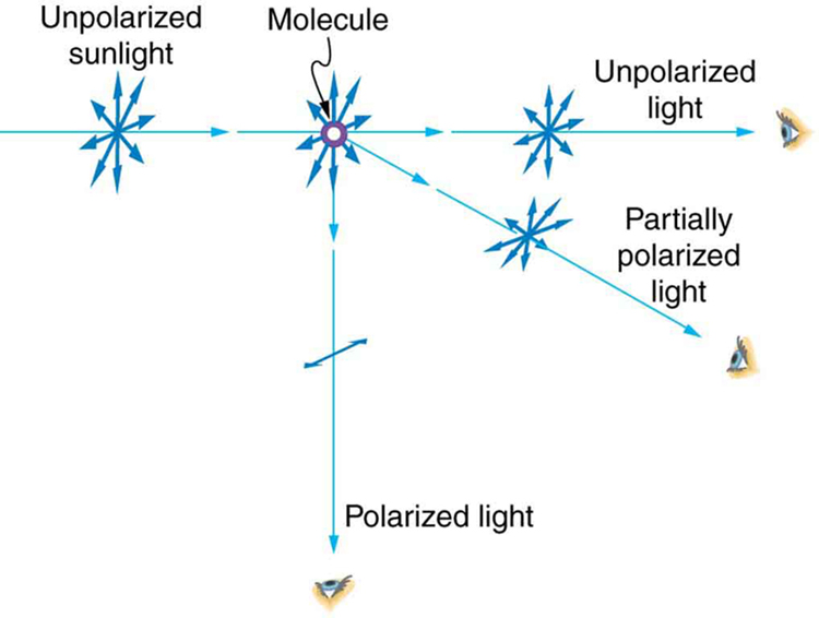
If you hold your Polaroid sunglasses in front of you and rotate them while looking at blue sky, you will see the sky get bright and dim. This is a clear indication that light scattered by air is partially polarized. Figure 11 helps illustrate how this happens. Since light is a transverse EM wave, it vibrates the electrons of air molecules perpendicular to the direction it is traveling. The electrons then radiate like small antennae. Since they are oscillating perpendicular to the direction of the light ray, they produce EM radiation that is polarized perpendicular to the direction of the ray. When viewing the light along a line perpendicular to the original ray, as in Figure 11, there can be no polarization in the scattered light parallel to the original ray, because that would require the original ray to be a longitudinal wave. Along other directions, a component of the other polarization can be projected along the line of sight, and the scattered light will only be partially polarized. Furthermore, multiple scattering can bring light to your eyes from other directions and can contain different polarizations.
Photographs of the sky can be darkened by polarizing filters, a trick used by many photographers to make clouds brighter by contrast. Scattering from other particles, such as smoke or dust, can also polarize light. Detecting polarization in scattered EM waves can be a useful analytical tool in determining the scattering source.
There is a range of optical effects used in sunglasses. Besides being Polaroid, other sunglasses have colored pigments embedded in them, while others use non-reflective or even reflective coatings. A recent development is photochromic lenses, which darken in the sunlight and become clear indoors. Photochromic lenses are embedded with organic microcrystalline molecules that change their properties when exposed to UV in sunlight, but become clear in artificial lighting with no UV.
Take-Home Experiment: Polarization
Find Polaroid sunglasses and rotate one while holding the other still and look at different surfaces and objects. Explain your observations. What is the difference in angle from when you see a maximum intensity to when you see a minimum intensity? Find a reflective glass surface and do the same. At what angle does the glass need to be oriented to give minimum glare?
Liquid Crystals and Other Polarization Effects in Materials
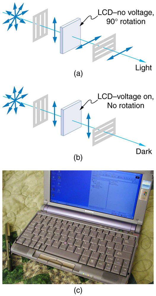
While you are undoubtedly aware of liquid crystal displays (LCDs) found in watches, calculators, computer screens, cellphones, flat screen televisions, and other myriad places, you may not be aware that they are based on polarization. Liquid crystals are so named because their molecules can be aligned even though they are in a liquid. Liquid crystals have the property that they can rotate the polarization of light passing through them by [latex]{90^{\circ}}[/latex]. Furthermore, this property can be turned off by the application of a voltage, as illustrated in Figure 12. It is possible to manipulate this characteristic quickly and in small well-defined regions to create the contrast patterns we see in so many LCD devices.
In flat screen LCD televisions, there is a large light at the back of the TV. The light travels to the front screen through millions of tiny units called pixels (picture elements). One of these is shown in Figure 12 (a) and (b). Each unit has three cells, with red, blue, or green filters, each controlled independently. When the voltage across a liquid crystal is switched off, the liquid crystal passes the light through the particular filter. One can vary the picture contrast by varying the strength of the voltage applied to the liquid crystal.
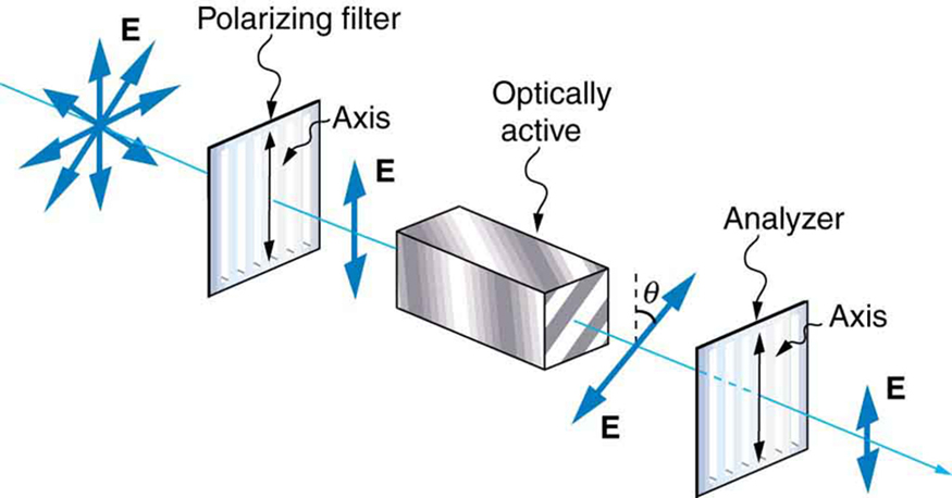
Many crystals and solutions rotate the plane of polarization of light passing through them. Such substances are said to be optically active. Examples include sugar water, insulin, and collagen (see Figure 13). In addition to depending on the type of substance, the amount and direction of rotation depends on a number of factors. Among these is the concentration of the substance, the distance the light travels through it, and the wavelength of light. Optical activity is due to the asymmetric shape of molecules in the substance, such as being helical. Measurements of the rotation of polarized light passing through substances can thus be used to measure concentrations, a standard technique for sugars. It can also give information on the shapes of molecules, such as proteins, and factors that affect their shapes, such as temperature and pH.
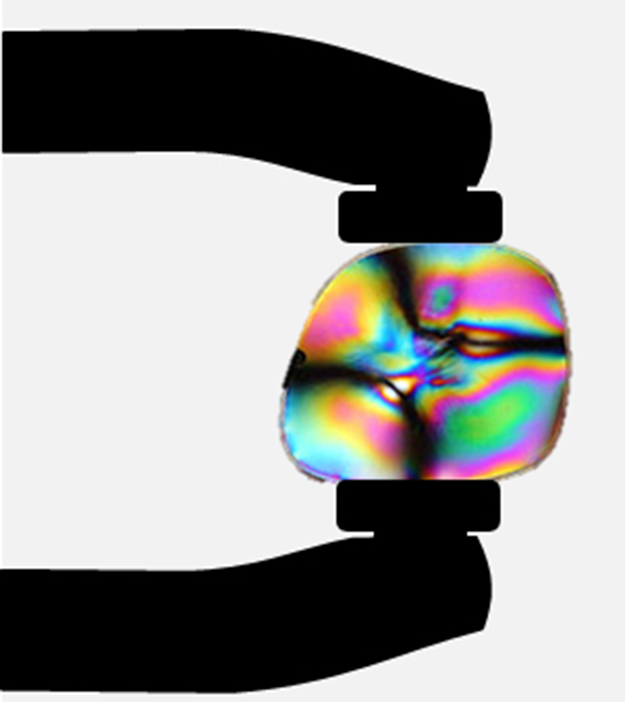
Glass and plastic become optically active when stressed; the greater the stress, the greater the effect. Optical stress analysis on complicated shapes can be performed by making plastic models of them and observing them through crossed filters, as seen in Figure 14. It is apparent that the effect depends on wavelength as well as stress. The wavelength dependence is sometimes also used for artistic purposes.
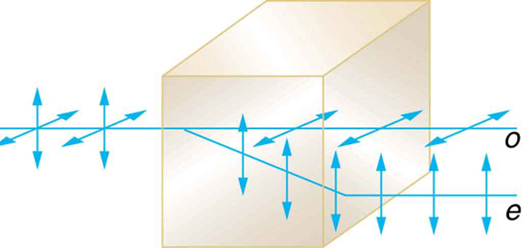
Another interesting phenomenon associated with polarized light is the ability of some crystals to split an unpolarized beam of light into two. Such crystals are said to be birefringent (see Figure 15). Each of the separated rays has a specific polarization. One behaves normally and is called the ordinary ray, whereas the other does not obey Snell’s law and is called the extraordinary ray. Birefringent crystals can be used to produce polarized beams from unpolarized light. Some birefringent materials preferentially absorb one of the polarizations. These materials are called dichroic and can produce polarization by this preferential absorption. This is fundamentally how polarizing filters and other polarizers work. The interested reader is invited to further pursue the numerous properties of materials related to polarization.
Section Summary
- Polarization is the attribute that wave oscillations have a definite direction relative to the direction of propagation of the wave.
- EM waves are transverse waves that may be polarized.
- The direction of polarization is defined to be the direction parallel to the electric field of the EM wave.
- Unpolarized light is composed of many rays having random polarization directions.
- Light can be polarized by passing it through a polarizing filter or other polarizing material. The intensity [latex]{I}[/latex] of polarized light after passing through a polarizing filter is [latex]{I = I_0 \;\text{cos}^2 \;\theta}[/latex], where [latex]{I_0}[/latex] is the original intensity and [latex]{\theta}[/latex] is the angle between the direction of polarization and the axis of the filter.
- Polarization is also produced by reflection.
- Brewster’s law states that reflected light will be completely polarized at the angle of reflection [latex]{\theta _{\text{b}}}[/latex], known as Brewster’s angle, given by a statement known as Brewster’s law: [latex]{\text{tan} \;\theta _{\text{b}} = \frac{n_2}{n_1}}[/latex], where [latex]{n_1}[/latex] is the medium in which the incident and reflected light travel and [latex]{n_2}[/latex] is the index of refraction of the medium that forms the interface that reflects the light.
- Polarization can also be produced by scattering.
- There are a number of types of optically active substances that rotate the direction of polarization of light passing through them.
Conceptual Questions
1: Under what circumstances is the phase of light changed by reflection? Is the phase related to polarization?
2: Can a sound wave in air be polarized? Explain.
3: No light passes through two perfect polarizing filters with perpendicular axes. However, if a third polarizing filter is placed between the original two, some light can pass. Why is this? Under what circumstances does most of the light pass?
4: Explain what happens to the energy carried by light that it is dimmed by passing it through two crossed polarizing filters.
5: When particles scattering light are much smaller than its wavelength, the amount of scattering is proportional to [latex]{1/ \lambda ^4}[/latex]. Does this mean there is more scattering for small [latex]{\lambda}[/latex] than large [latex]{\lambda}[/latex]? How does this relate to the fact that the sky is blue?
6: Using the information given in the preceding question, explain why sunsets are red.
7: When light is reflected at Brewster’s angle from a smooth surface, it is [latex]{100 \%}[/latex] polarized parallel to the surface. Part of the light will be refracted into the surface. Describe how you would do an experiment to determine the polarization of the refracted light. What direction would you expect the polarization to have and would you expect it to be [latex]{100 \%}[/latex]?
Problems & Exercises
1: What angle is needed between the direction of polarized light and the axis of a polarizing filter to cut its intensity in half?
2: The angle between the axes of two polarizing filters is [latex]{45.0^{\circ}}[/latex]. By how much does the second filter reduce the intensity of the light coming through the first?
3: If you have completely polarized light of intensity [latex]{150 \;\text{W/m}^2}[/latex], what will its intensity be after passing through a polarizing filter with its axis at an [latex]{89.0^{\circ}}[/latex] angle to the light’s polarization direction?
4: What angle would the axis of a polarizing filter need to make with the direction of polarized light of intensity [latex]{1.00 \;\text{kW/m}^2}[/latex] to reduce the intensity to [latex]{10.0 \;\text{W/m}^2}[/latex]?
5: At the end of Example 1, it was stated that the intensity of polarized light is reduced to [latex]{90.0 \%}[/latex] of its original value by passing through a polarizing filter with its axis at an angle of [latex]{18.4^{\circ}}[/latex] to the direction of polarization. Verify this statement.
6: Show that if you have three polarizing filters, with the second at an angle of [latex]{45^{\circ}}[/latex] to the first and the third at an angle of [latex]{90.0^{\circ}}[/latex] to the first, the intensity of light passed by the first will be reduced to [latex]{25.0 \%}[/latex] of its value. (This is in contrast to having only the first and third, which reduces the intensity to zero, so that placing the second between them increases the intensity of the transmitted light.)
7: Prove that, if II is the intensity of light transmitted by two polarizing filters with axes at an angle [latex]{\theta}[/latex] and [latex]{I^{\prime}} is the intensity when the axes are at an angle [latex]{90.0^{\circ} - \theta}[/latex], then [latex]{I + I^{\prime} = I_0}[/latex], the original intensity. (Hint: Use the trigonometric identities [latex]{\text{cos} \; (90.0^{\circ} - \theta) = \text{sin} \;\theta}[/latex] and [latex]{\text{cos}^2 \;\theta + \text{sin}^2 \;\theta = 1}[/latex].)
8: At what angle will light reflected from diamond be completely polarized?
9: What is Brewster’s angle for light traveling in water that is reflected from crown glass?
10: A scuba diver sees light reflected from the water’s surface. At what angle will this light be completely polarized?
11: At what angle is light inside crown glass completely polarized when reflected from water, as in a fish tank?
12: Light reflected at [latex]{55.6 ^{\circ}}[/latex] from a window is completely polarized. What is the window’s index of refraction and the likely substance of which it is made?
13: (a) Light reflected at [latex]{62.5 ^{\circ}}[/latex] from a gemstone in a ring is completely polarized. Can the gem be a diamond? (b) At what angle would the light be completely polarized if the gem was in water?
14: If [latex]{\theta_{\text{b}}}[/latex] is Brewster’s angle for light reflected from the top of an interface between two substances, and [latex]{{\theta ^{\prime}}_{\text{b}}}[/latex] is Brewster’s angle for light reflected from below, prove that [latex]{\theta _{\text{b}} + {\theta ^{\prime}}_{\text{b}} = 90.0^{\circ}}[/latex].
15: Integrated Concepts
If a polarizing filter reduces the intensity of polarized light to [latex]{50.0 \%}[/latex] of its original value, by how much are the electric and magnetic fields reduced?
16: Integrated Concepts
Suppose you put on two pairs of Polaroid sunglasses with their axes at an angle of [latex]{15.0 ^{\circ}}[/latex]. How much longer will it take the light to deposit a given amount of energy in your eye compared with a single pair of sunglasses? Assume the lenses are clear except for their polarizing characteristics.
17: Integrated Concepts
(a) On a day when the intensity of sunlight is [latex]{1.00 \;\text{kW/m}^2}[/latex], a circular lens 0.200 m in diameter focuses light onto water in a black beaker. Two polarizing sheets of plastic are placed in front of the lens with their axes at an angle of [latex]{20.0 ^{\circ}}[/latex]. Assuming the sunlight is unpolarized and the polarizers are [latex]{100 \% }[/latex] efficient, what is the initial rate of heating of the water in [latex]{^{\circ} \;\text{C/s}}[/latex], assuming it is [latex]{80.0 \%}[/latex] absorbed? The aluminum beaker has a mass of 30.0 grams and contains 250 grams of water. (b) Do the polarizing filters get hot? Explain.
Glossary
- axis of a polarizing filter
- the direction along which the filter passes the electric field of an EM wave
- birefringent
- crystals that split an unpolarized beam of light into two beams
- Brewster’s angle
- [latex]{\theta _{\text{b}} = \;\text{tan}^{-1} \frac{n_2}{n_1}}[/latex], where [latex]{n_2}[/latex] is the index of refraction of the medium from which the light is reflected and n1n1 is the index of refraction of the medium in which the reflected light travels
- Brewster’s law
- [latex]{\text{tan} \;\theta _{\text{b}} = \frac{n_2}{n_1}}[/latex], where
n1n1 is the medium in which the incident and reflected light travel and n2n2 is the index of refraction of the medium that forms the interface that reflects the light
- direction of polarization
- the direction parallel to the electric field for EM waves
- horizontally polarized
- the oscillations are in a horizontal plane
- optically active
- substances that rotate the plane of polarization of light passing through them
- polarization
- the attribute that wave oscillations have a definite direction relative to the direction of propagation of the wave
- polarized
- waves having the electric and magnetic field oscillations in a definite direction
- reflected light that is completely polarized
- light reflected at the angle of reflection [latex]{\theta _{\text{b}}}[/latex], known as Brewster’s angle
- unpolarized
- waves that are randomly polarized
- vertically polarized
- the oscillations are in a vertical plane
Solutions
Problems & Exercises
1: [latex]{45.0^{\circ}}[/latex]
3: [latex]{45.7 \;\text{mW/m}^2}[/latex]
5: [latex]{90.0 \%}[/latex]
7: [latex]{I_0}[/latex]
9: [latex]{48.8^{\circ}}[/latex]
11: [latex]{41.2 ^{\circ}}[/latex]
13: (a) 1.92, not diamond (Zircon)
(b) [latex]{55.2 ^{\circ}}[/latex]
15: [latex]{B_2 = 0.707 \; B_1}[/latex]
17: (a) [latex]{2.07 \times 10^{-2} \; ^{\circ} \text{C/s}}[/latex]
(b) Yes, the polarizing filters get hot because they absorb some of the lost energy from the sunlight.
