
Chapter 22 Magnetism
22.6 The Hall Effect
Summary
- Describe the Hall effect.
- Calculate the Hall emf across a current-carrying conductor.
We have seen effects of a magnetic field on free-moving charges. The magnetic field also affects charges moving in a conductor. One result is the Hall effect, which has important implications and applications.
Figure 1 shows what happens to charges moving through a conductor in a magnetic field. The field is perpendicular to the electron drift velocity and to the width of the conductor. Note that conventional current is to the right in both parts of the figure. In part (a), electrons carry the current and move to the left. In part (b), positive charges carry the current and move to the right. Moving electrons feel a magnetic force toward one side of the conductor, leaving a net positive charge on the other side. This separation of charge creates a voltage [latex]{\varepsilon}[/latex], known as the Hall emf, across the conductor. The creation of a voltage across a current-carrying conductor by a magnetic field is known as the Hall effect, after Edwin Hall, the American physicist who discovered it in 1879.
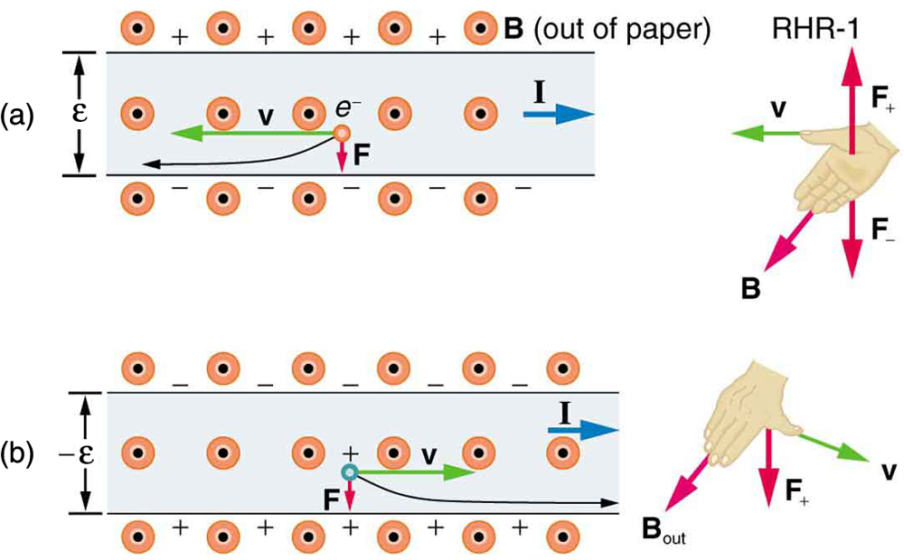
One very important use of the Hall effect is to determine whether positive or negative charges carries the current. Note that in Figure 1(b), where positive charges carry the current, the Hall emf has the sign opposite to when negative charges carry the current. Historically, the Hall effect was used to show that electrons carry current in metals and it also shows that positive charges carry current in some semiconductors. The Hall effect is used today as a research tool to probe the movement of charges, their drift velocities and densities, and so on, in materials. In 1980, it was discovered that the Hall effect is quantized, an example of quantum behavior in a macroscopic object.
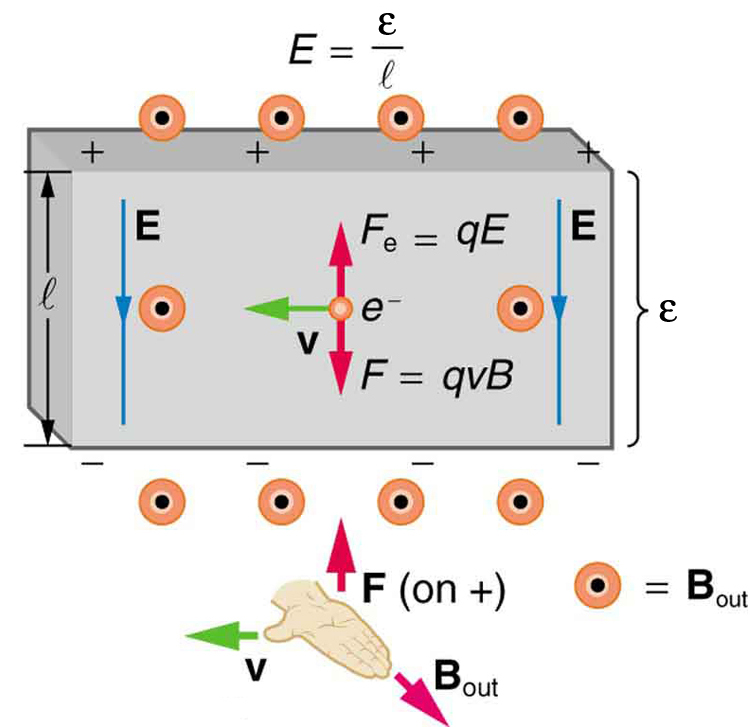
The Hall effect has other uses that range from the determination of blood flow rate to precision measurement of magnetic field strength. To examine these quantitatively, we need an expression for the Hall emf, [latex]{\varepsilon}[/latex], across a conductor. Consider the balance of forces on a moving charge in a situation where [latex]{B}[/latex], [latex]{v}[/latex], and [latex]{l}[/latex] are mutually perpendicular, such as shown in Figure 2. Although the magnetic force moves negative charges to one side, they cannot build up without limit. The electric field caused by their separation opposes the magnetic force, [latex]{F = qvB}[/latex], and the electric force, [latex]{F_e = qE}[/latex], eventually grows to equal it. That is,
or
Note that the electric field [latex]{E}[/latex] is uniform across the conductor because the magnetic field [latex]{B}[/latex] is uniform, as is the conductor. For a uniform electric field, the relationship between electric field and voltage is [latex]{E = \varepsilon /l}[/latex], where [latex]{l}[/latex] is the width of the conductor and [latex]{\varepsilon}[/latex] is the Hall emf. Entering this into the last expression gives
Solving this for the Hall emf yields
where [latex]{\varepsilon}[/latex] is the Hall effect voltage across a conductor of width [latex]{l}[/latex] through which charges move at a speed [latex]{v}[/latex].
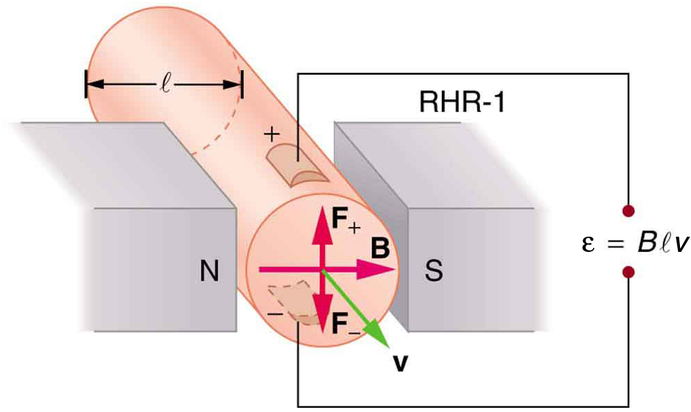
One of the most common uses of the Hall effect is in the measurement of magnetic field strength [latex]{B}[/latex]. Such devices, called Hall probes, can be made very small, allowing fine position mapping. Hall probes can also be made very accurate, usually accomplished by careful calibration. Another application of the Hall effect is to measure fluid flow in any fluid that has free charges (most do). (See Figure 3.) A magnetic field applied perpendicular to the flow direction produces a Hall emf [latex]{\varepsilon}[/latex] as shown. Note that the sign of [latex]{\varepsilon}[/latex] depends not on the sign of the charges, but only on the directions of [latex]{B}[/latex] and [latex]{v}[/latex]. The magnitude of the Hall emf is [latex]{\varepsilon = Blv}[/latex], where [latex]{l}[/latex] is the pipe diameter, so that the average velocity [latex]{v}[/latex] can be determined from [latex]{\varepsilon}[/latex] providing the other factors are known.
Calculating the Hall emf: Hall Effect for Blood Flow
A Hall effect flow probe is placed on an artery, applying a 0.100-T magnetic field across it, in a setup similar to that in Figure 3. What is the Hall emf, given the vessel’s inside diameter is 4.00 mm and the average blood velocity is 20.0 cm/s?
Strategy
Because [latex]{B}[/latex], [latex]{v}[/latex], and [latex]{l}[/latex] are mutually perpendicular, the equation [latex]{\varepsilon =Blv}[/latex] can be used to find [latex]{\varepsilon}[/latex].
Solution
Entering the given values for [latex]{B}[/latex], [latex]{v}[/latex], and [latex]{l}[/latex] gives
Discussion
This is the average voltage output. Instantaneous voltage varies with pulsating blood flow. The voltage is small in this type of measurement. εε size 12{ε} {} is particularly difficult to measure, because there are voltages associated with heart action (ECG voltages) that are on the order of millivolts. In practice, this difficulty is overcome by applying an AC magnetic field, so that the Hall emf is AC with the same frequency. An amplifier can be very selective in picking out only the appropriate frequency, eliminating signals and noise at other frequencies.
Section Summary
- The Hall effect is the creation of voltage [latex]{\varepsilon}[/latex], known as the Hall emf, across a current-carrying conductor by a magnetic field.
- The Hall emf is given by
[latex]{\varepsilon = Blv \; (B, \; v, \;\text{and} \; l, \;\text{mutually perpendicular})}[/latex]
for a conductor of width [latex]{l}[/latex] through which charges move at a speed [latex]{v}[/latex].
Conceptual Questions
1: Discuss how the Hall effect could be used to obtain information on free charge density in a conductor. (Hint: Consider how drift velocity and current are related.)
Problems & Exercises
1: A large water main is 2.50 m in diameter and the average water velocity is 6.00 m/s. Find the Hall voltage produced if the pipe runs perpendicular to the Earth’s [latex]{5.00 \times 10^{-5} - \text{T}}[/latex] field.
2: What Hall voltage is produced by a 0.200-T field applied across a 2.60-cm-diameter aorta when blood velocity is 60.0 cm/s?
3: (a) What is the speed of a supersonic aircraft with a 17.0-m wingspan, if it experiences a 1.60-V Hall voltage between its wing tips when in level flight over the north magnetic pole, where the Earth’s field strength is [latex]{8.00 \times 10^{-5} \;\text{T}}[/latex]? (b) Explain why very little current flows as a result of this Hall voltage.
4: A nonmechanical water meter could utilize the Hall effect by applying a magnetic field across a metal pipe and measuring the Hall voltage produced. What is the average fluid velocity in a 3.00-cm-diameter pipe, if a 0.500-T field across it creates a 60.0-mV Hall voltage?
5: Calculate the Hall voltage induced on a patient’s heart while being scanned by an MRI unit. Approximate the conducting path on the heart wall by a wire 7.50 cm long that moves at 10.0 cm/s perpendicular to a 1.50-T magnetic field.
6: A Hall probe calibrated to read [latex]{1.00 \;\mu \text{V}}[/latex] when placed in a 2.00-T field is placed in a 0.150-T field. What is its output voltage?
7: Using information in Chapter 20.3 Resistance and Resistivity Table 2, what would the Hall voltage be if a 2.00-T field is applied across a 10-gauge copper wire (2.588 mm in diameter) carrying a 20.0-A current?
8: Show that the Hall voltage across wires made of the same material, carrying identical currents, and subjected to the same magnetic field is inversely proportional to their diameters. (Hint: Consider how drift velocity depends on wire diameter.)
9: A patient with a pacemaker is mistakenly being scanned for an MRI image. A 10.0-cm-long section of pacemaker wire moves at a speed of 10.0 cm/s perpendicular to the MRI unit’s magnetic field and a 20.0-mV Hall voltage is induced. What is the magnetic field strength?
Glossary
- Hall effect
- the creation of voltage across a current-carrying conductor by a magnetic field
- Hall emf
- the electromotive force created by a current-carrying conductor by a magnetic field, [latex]{\varepsilon = Blv}[/latex]
Solutions
Problems & Exercises
1: [latex]{7.50 \times 10^{-4} \;\text{V}}[/latex]
3: (a) [latex]{1.18 \times 10^3 \;\text{m/s}}[/latex]
(b) Once established, the Hall emf pushes charges one direction and the magnetic force acts in the opposite direction resulting in no net force on the charges. Therefore, no current flows in the direction of the Hall emf. This is the same as in a current-carrying conductor—current does not flow in the direction of the Hall emf.
5: 11.3 mV
7: [latex]{1.16 \;\mu \text{V}}[/latex]
9: 2.00 T
