
Chapter 15 Thermodynamics
15.4 Carnot’s Perfect Heat Engine: The Second Law of Thermodynamics Restated
Summary
- Identify a Carnot cycle.
- Calculate maximum theoretical efficiency of a nuclear reactor.
- Explain how dissipative processes affect the ideal Carnot engine.
We know from the second law of thermodynamics that a heat engine cannot be 100% efficient, since there must always be some heat transfer [latex]{Q_{\text{c}}}[/latex] to the environment, which is often called waste heat. How efficient, then, can a heat engine be? This question was answered at a theoretical level in 1824 by a young French engineer, Sadi Carnot (1796–1832), in his study of the then-emerging heat engine technology crucial to the Industrial Revolution. He devised a theoretical cycle, now called the Carnot cycle, which is the most efficient cyclical process possible. The second law of thermodynamics can be restated in terms of the Carnot cycle, and so what Carnot actually discovered was this fundamental law. Any heat engine employing the Carnot cycle is called a Carnot engine.
What is crucial to the Carnot cycle—and, in fact, defines it—is that only reversible processes are used. Irreversible processes involve dissipative factors, such as friction and turbulence. This increases heat transfer [latex]{Q_{\text{c}}}[/latex] to the environment and reduces the efficiency of the engine. Obviously, then, reversible processes are superior.
CARNOT ENGINE
Stated in terms of reversible processes, the second law of thermodynamics has a third form:
A Carnot engine operating between two given temperatures has the greatest possible efficiency of any heat engine operating between these two temperatures. Furthermore, all engines employing only reversible processes have this same maximum efficiency when operating between the same given temperatures.
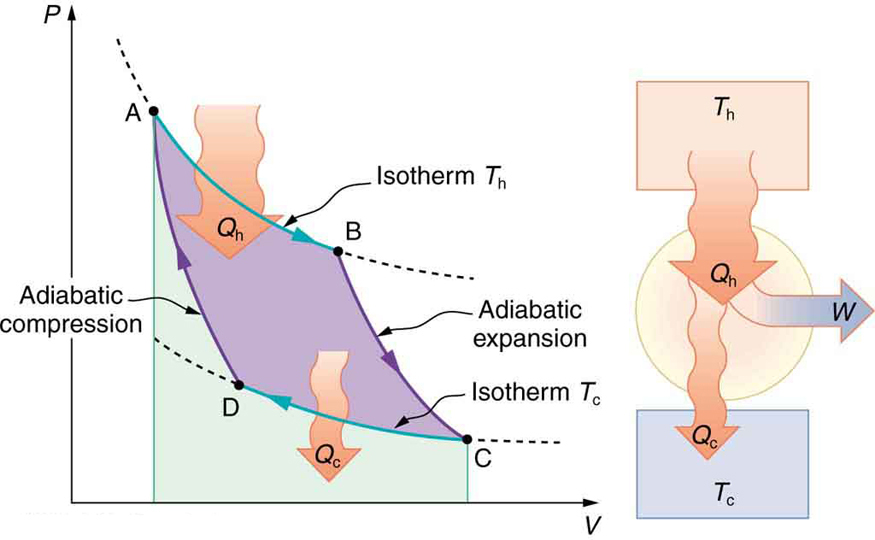
Figure 2 shows the [latex]{PV}[/latex] diagram for a Carnot cycle. The cycle comprises two isothermal and two adiabatic processes. Recall that both isothermal and adiabatic processes are, in principle, reversible.
Carnot also determined the efficiency of a perfect heat engine—that is, a Carnot engine. It is always true that the efficiency of a cyclical heat engine is given by:
What Carnot found was that for a perfect heat engine, the ratio [latex]{Q_{\text{c}}/Q_{\text{h}}}[/latex] equals the ratio of the absolute temperatures of the heat reservoirs. That is, [latex]{Q_{\text{c}}/Q_{\text{h}}=T_{\text{c}}/T_{\text{h}}}[/latex] for a Carnot engine, so that the maximum or Carnot efficiency [latex]{Eff_{\text{C}}}[/latex] is given by
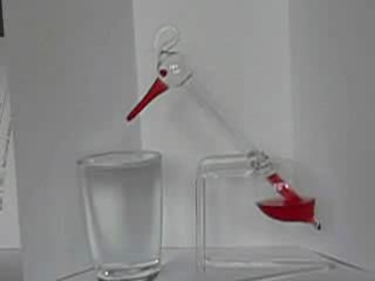
where [latex]{T_{\text{h}}}[/latex] and [latex]{T_{\text{c}}}[/latex] are in kelvins (or any other absolute temperature scale). No real heat engine can do as well as the Carnot efficiency—an actual efficiency of about 0.7 of this maximum is usually the best that can be accomplished. But the ideal Carnot engine, like the drinking bird above, while a fascinating novelty, has zero power. This makes it unrealistic for any applications.
Carnot’s interesting result implies that 100% efficiency would be possible only if [latex]{T_{\text{c}}=0\text{ K}}[/latex] —that is, only if the cold reservoir were at absolute zero, a practical and theoretical impossibility. But the physical implication is this—the only way to have all heat transfer go into doing work is to remove all thermal energy, and this requires a cold reservoir at absolute zero.
It is also apparent that the greatest efficiencies are obtained when the ratio [latex]{T_{\text{c}}/T_{\text{h}}}[/latex] is as small as possible. Just as discussed for the Otto cycle in the previous section, this means that efficiency is greatest for the highest possible temperature of the hot reservoir and lowest possible temperature of the cold reservoir. (This setup increases the area inside the closed loop on the [latex]{PV}[/latex] diagram; also, it seems reasonable that the greater the temperature difference, the easier it is to divert the heat transfer to work.) The actual reservoir temperatures of a heat engine are usually related to the type of heat source and the temperature of the environment into which heat transfer occurs. Consider the following example.
Example 1: Maximum Theoretical Efficiency for a Nuclear Reactor
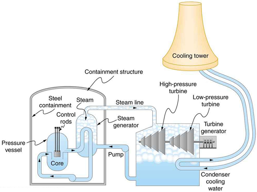
A nuclear power reactor has pressurized water at [latex]{300^{\circ}\text{C}}.[/latex] (Higher temperatures are theoretically possible but practically not, due to limitations with materials used in the reactor.) Heat transfer from this water is a complex process (see Figure 3). Steam, produced in the steam generator, is used to drive the turbine-generators. Eventually the steam is condensed to water at [latex]{27^{\circ}\text{C}}[/latex] and then heated again to start the cycle over. Calculate the maximum theoretical efficiency for a heat engine operating between these two temperatures.
Strategy
Since temperatures are given for the hot and cold reservoirs of this heat engine, [latex]{Eff_{\text{C}}=1-\frac{T_{\text{c}}}{T_{\text{h}}}}[/latex] can be used to calculate the Carnot (maximum theoretical) efficiency. Those temperatures must first be converted to kelvins.
Solution
The hot and cold reservoir temperatures are given as [latex]{300^{\circ}\text{C}}[/latex] and [latex]{27.0^{\circ}\text{C}},[/latex] respectively. In kelvins, then, [latex]{T_{\text{h}}=573\text{ K}}[/latex] and [latex]{T_{\text{c}}=300\text{ K}},[/latex] so that the maximum efficiency is
Thus,
Discussion
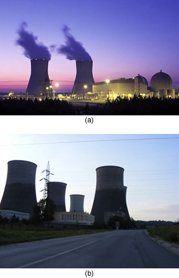
A typical nuclear power station’s actual efficiency is about 35%, a little better than 0.7 times the maximum possible value, a tribute to superior engineering. Electrical power stations fired by coal, oil, and natural gas have greater actual efficiencies (about 42%), because their boilers can reach higher temperatures and pressures. The cold reservoir temperature in any of these power stations is limited by the local environment. Figure 4 shows (a) the exterior of a nuclear power station and (b) the exterior of a coal-fired power station. Both have cooling towers into which water from the condenser enters the tower near the top and is sprayed downward, cooled by evaporation.
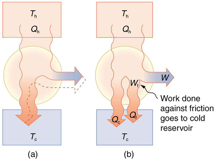
Since all real processes are irreversible, the actual efficiency of a heat engine can never be as great as that of a Carnot engine, as illustrated in Figure 5(a). Even with the best heat engine possible, there are always dissipative processes in peripheral equipment, such as electrical transformers or car transmissions. These further reduce the overall efficiency by converting some of the engine’s work output back into heat transfer, as shown in Figure 5(b).
Section Summary
- The Carnot cycle is a theoretical cycle that is the most efficient cyclical process possible. Any engine using the Carnot cycle, which uses only reversible processes (adiabatic and isothermal), is known as a Carnot engine.
- Any engine that uses the Carnot cycle enjoys the maximum theoretical efficiency.
- While Carnot engines are ideal engines, in reality, no engine achieves Carnot’s theoretical maximum efficiency, since dissipative processes, such as friction, play a role. Carnot cycles without heat loss may be possible at absolute zero, but this has never been seen in nature.
Conceptual Questions
1: Think about the drinking bird at the beginning of this section (Figure 1). Although the bird enjoys the theoretical maximum efficiency possible, if left to its own devices over time, the bird will cease “drinking.” What are some of the dissipative processes that might cause the bird’s motion to cease?
2: Can improved engineering and materials be employed in heat engines to reduce heat transfer into the environment? Can they eliminate heat transfer into the environment entirely?
3: Does the second law of thermodynamics alter the conservation of energy principle?
Problems & Exercises
1: A certain gasoline engine has an efficiency of 30.0%. What would the hot reservoir temperature be for a Carnot engine having that efficiency, if it operates with a cold reservoir temperature of [latex]{200^{\circ}\text{C}}?[/latex]
2: A gas-cooled nuclear reactor operates between hot and cold reservoir temperatures of [latex]{700^{\circ}\text{C}}[/latex] and [latex]{27.0^{\circ}\text{C}}.[/latex] (a) What is the maximum efficiency of a heat engine operating between these temperatures? (b) Find the ratio of this efficiency to the Carnot efficiency of a standard nuclear reactor (found in Example 1).
3: (a) What is the hot reservoir temperature of a Carnot engine that has an efficiency of 42.0% and a cold reservoir temperature of [latex]{27.0^{\circ}\text{C}}?[/latex] (b) What must the hot reservoir temperature be for a real heat engine that achieves 0.700 of the maximum efficiency, but still has an efficiency of 42.0% (and a cold reservoir at [latex]{27.0^{\circ}\text{C}}[/latex] )? (c) Does your answer imply practical limits to the efficiency of car gasoline engines?
4: Steam locomotives have an efficiency of 17.0% and operate with a hot steam temperature of [latex]{425^{\circ}\text{C}}.[/latex] (a) What would the cold reservoir temperature be if this were a Carnot engine? (b) What would the maximum efficiency of this steam engine be if its cold reservoir temperature were [latex]{150^{\circ}\text{C}}?[/latex]
5: Practical steam engines utilize [latex]{450^{\circ}\text{C}}[/latex] steam, which is later exhausted at [latex]{270^{\circ}\text{C}}.[/latex] (a) What is the maximum efficiency that such a heat engine can have? (b) Since [latex]{270^{\circ}\text{C}}[/latex] steam is still quite hot, a second steam engine is sometimes operated using the exhaust of the first. What is the maximum efficiency of the second engine if its exhaust has a temperature of [latex]{150^{\circ}\text{C}}?[/latex] (c) What is the overall efficiency of the two engines? (d) Show that this is the same efficiency as a single Carnot engine operating between [latex]{450^{\circ}\text{C}}[/latex] and [latex]{150^{\circ}\text{C}}.[/latex] Explicitly show how you follow the steps in the Chapter 15.5 Problem-Solving Strategies for Thermodynamics.
6: A coal-fired electrical power station has an efficiency of 38%. The temperature of the steam leaving the boiler is [latex]{550^{\circ}\text{C}}.[/latex] What percentage of the maximum efficiency does this station obtain? (Assume the temperature of the environment is [latex]{20^{\circ}\text{C}}[/latex].)
7: Would you be willing to financially back an inventor who is marketing a device that she claims has 25 kJ of heat transfer at 600 K, has heat transfer to the environment at 300 K, and does 12 kJ of work? Explain your answer.
8: Unreasonable Results
(a) Suppose you want to design a steam engine that has heat transfer to the environment at [latex]{270^{\circ}\text{C}}[/latex] and has a Carnot efficiency of 0.800. What temperature of hot steam must you use? (b) What is unreasonable about the temperature? (c) Which premise is unreasonable?
9: Unreasonable Results
Calculate the cold reservoir temperature of a steam engine that uses hot steam at [latex]{450^{\circ}\text{C}}[/latex] and has a Carnot efficiency of 0.700. (b) What is unreasonable about the temperature? (c) Which premise is unreasonable?
Glossary
- Carnot cycle
- a cyclical process that uses only reversible processes, the adiabatic and isothermal processes
- Carnot engine
- a heat engine that uses a Carnot cycle
- Carnot efficiency
- the maximum theoretical efficiency for a heat engine
Solutions
Problems & Exercises
1:
[latex]{403^{\circ}\text{C}}[/latex]
3:
(a) [latex]{244^{\circ}\text{C}}[/latex]
(b) [latex]{477^{\circ}\text{C}}[/latex]
(c)Yes, since automobiles engines cannot get too hot without overheating, their efficiency is limited.
5:
(a) [latex]{Eff_1=1-\frac{T_{\text{c,1}}}{T_{\text{h,1}}}=1-\frac{543\text{ K}}{723\text{ K}}=0.249\text{ or }24.9\%}[/latex]
(b) [latex]{Eff_2=1-\frac{423 K}{543 K}=0.221\text{ or }22.1\%}[/latex]
(c) [latex]{Eff_1=1-\frac{T_{\text{c,1}}}{T_{\text{h,1}}}\Rightarrow{T}_{\text{c,1}}=T_{\text{h,1}}(1,\:-,\:eff_1)\textbf{ similarly, }T_{\textbf{c,2}}=T_{\textbf{h,2}}(1-Eff_2)}[/latex]
[latex]\begin{array}{ll} {} & {T_{\textbf{c,2}}=T_{\text{h,1}}(1-Eff_1)(1-Eff_2)\equiv{T}_{\text{h,1}}(1-Eff_{\text{overall}})} \\ {\text{using }T_{\textbf{h,2}}=T_{\text{c,1}}\text{ in above equation gives}} & {\therefore(1-Eff_{\text{overall}})=(1-Eff_1)(1-Eff_2)} \\ {} & {Eff_{\text{overall}}=1-(1-0.249)(1-0.221)=41.5\%} \end{array}[/latex]
(d) [latex]{Eff_{\text{overall}}=1-\frac{423\text{ K}}{723\text{ K}}=0.415\text{ or }41.5\%}[/latex]
7:
The heat transfer to the cold reservoir is [latex]{Q_{\text{c}}=Q_{\text{h}}-W=25\text{ kJ}-12\text{ kJ}=13\text{ kJ}},[/latex] so the efficiency is [latex]{Eff=1-\frac{Q_{\text{c}}}{Q_{\text{h}}}=1-\frac{13\text{ kJ}}{25\text{ kJ}}=0.48}.[/latex] The Carnot efficiency is [latex]{Eff_{\text{C}}=1-\frac{T_{\text{c}}}{T_{\text{h}}}=1-\frac{300\text{ K}}{600\text{ K}}=0.50}.[/latex] The actual efficiency is 96% of the Carnot efficiency, which is much higher than the best-ever achieved of about 70%, so her scheme is likely to be fraudulent.
9:
(a) [latex]{-56.3^{\circ}\text{C}}[/latex]
(b) The temperature is too cold for the output of a steam engine (the local environment). It is below the freezing point of water.
(c) The assumed efficiency is too high.
