
Chapter 21 Circuits and DC Instruments
21.5 Null Measurements
Summary
- Explain why a null measurement device is more accurate than a standard voltmeter or ammeter.
- Demonstrate how a Wheatstone bridge can be used to accurately calculate the resistance in a circuit.
Standard measurements of voltage and current alter the circuit being measured, introducing uncertainties in the measurements. Voltmeters draw some extra current, whereas ammeters reduce current flow. Null measurements balance voltages so that there is no current flowing through the measuring device and, therefore, no alteration of the circuit being measured.
Null measurements are generally more accurate but are also more complex than the use of standard voltmeters and ammeters, and they still have limits to their precision. In this module, we shall consider a few specific types of null measurements, because they are common and interesting, and they further illuminate principles of electric circuits.
The Potentiometer
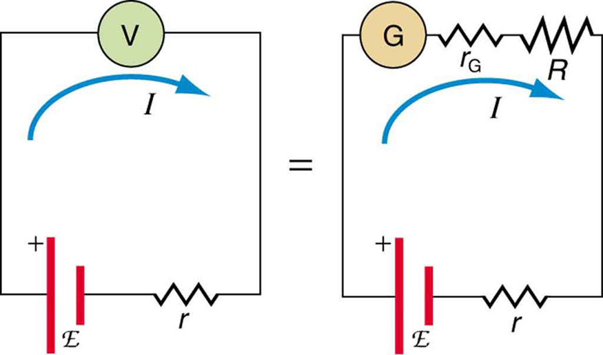
Suppose you wish to measure the emf of a battery. Consider what happens if you connect the battery directly to a standard voltmeter as shown in Figure 1. (Once we note the problems with this measurement, we will examine a null measurement that improves accuracy.) As discussed before, the actual quantity measured is the terminal voltage [latex]{V}[/latex], which is related to the emf of the battery by [latex]{V = \text{emf} - Ir}[/latex], where [latex]{I}[/latex] is the current that flows and [latex]{r}[/latex] is the internal resistance of the battery.
The emf could be accurately calculated if [latex]{r}[/latex] were very accurately known, but it is usually not. If the current [latex]{I}[/latex] could be made zero, then [latex]{V = \text{emf}}[/latex], and so emf could be directly measured. However, standard voltmeters need a current to operate; thus, another technique is needed.
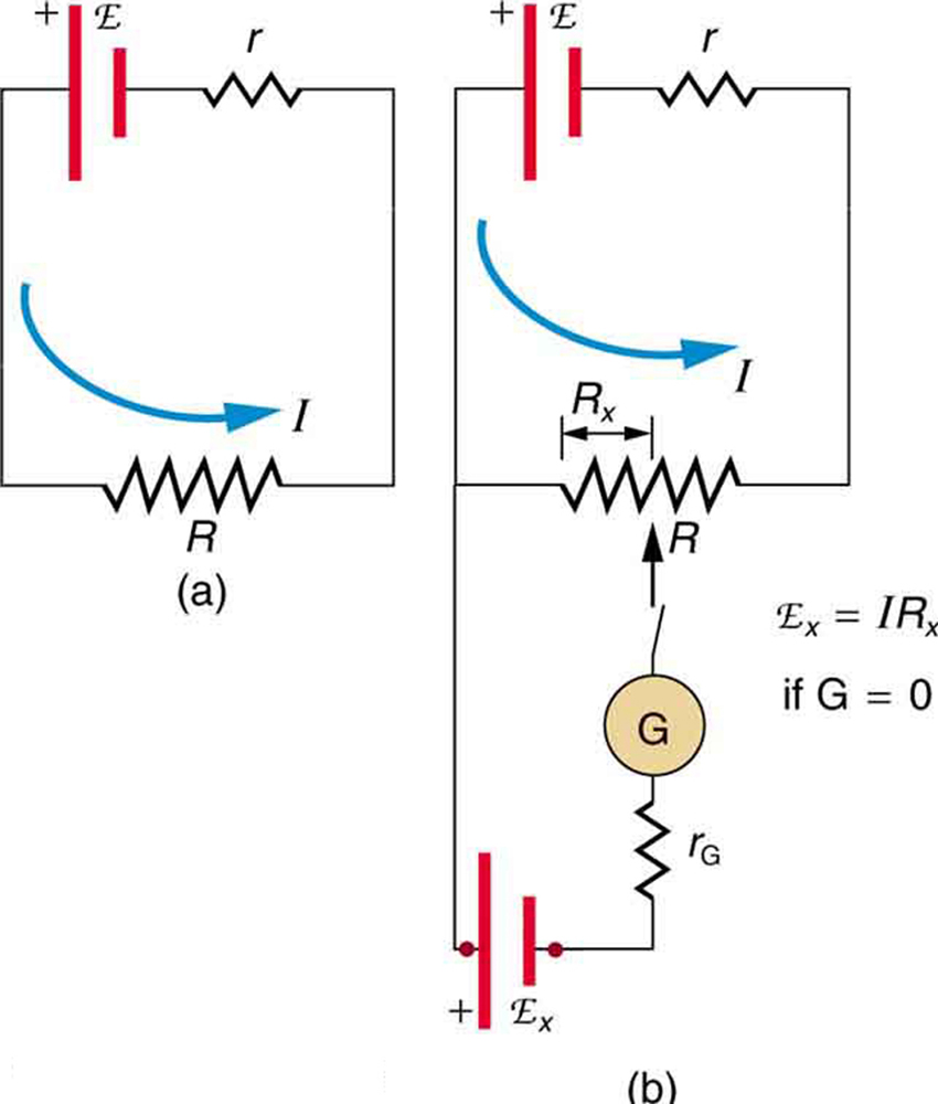
A potentiometer is a null measurement device for measuring potentials (voltages). (See Figure 2.) A voltage source is connected to a resistor [latex]{R}[/latex], say, a long wire, and passes a constant current through it. There is a steady drop in potential (an [latex]{IR}[/latex] drop) along the wire, so that a variable potential can be obtained by making contact at varying locations along the wire.
Figure 2(b) shows an unknown [latex]\text{emf}_{\text{x}}[/latex] (represented by script [latex]{E_{\text{x}}}[/latex] in the figure) connected in series with a galvanometer. Note that [latex]\text{emf}_{\text{x}}[/latex] opposes the other voltage source. The location of the contact point (see the arrow on the drawing) is adjusted until the galvanometer reads zero. When the galvanometer reads zero, [latex]{\text{emf}_{\text{x}} = IR_{\text{x}}}[/latex] is the resistance of the section of wire up to the contact point. Since no current flows through the galvanometer, none flows through the unknown emf, and so [latex]\text{emf}_{\text{x}}[/latex] is directly sensed.
Now, a very precisely known standard [latex]\text{emf}_{\text{s}}[/latex] is substituted for [latex]\text{emf}_{\text{x}}[/latex], and the contact point is adjusted until the galvanometer again reads zero, so that [latex]{\text{emf}_{\text{s}} = IR_{\text{s}}}[/latex]. In both cases, no current passes through the galvanometer, and so the current [latex]{I}[/latex] through the long wire is the same. Upon taking the ratio [latex]{\frac{\text{emf}_{\text{x}}}{\text{emf}_{\text{s}}}}[/latex], [latex]{I}[/latex] cancels, giving
Solving for [latex]\text{emf}_{\text{x}}[/latex] gives
Because a long uniform wire is used for [latex]{R}[/latex], the ratio of resistances [latex]{R_{\text{x}}/R_{\text{s}}}[/latex] is the same as the ratio of the lengths of wire that zero the galvanometer for each emf. The three quantities on the right-hand side of the equation are now known or measured, and [latex]\text{emf}_{\text{x}}[/latex] can be calculated. The uncertainty in this calculation can be considerably smaller than when using a voltmeter directly, but it is not zero. There is always some uncertainty in the ratio of resistances [latex]{R_{\text{x}}/R_{\text{s}}}[/latex] and in the standard [latex]\text{emf}_{\text{s}}[/latex]. Furthermore, it is not possible to tell when the galvanometer reads exactly zero, which introduces error into both [latex]{R_{\text{x}}}[/latex] and [latex]{R_{\text{s}}}[/latex], and may also affect the current [latex]{I}[/latex].
Resistance Measurements and the Wheatstone Bridge
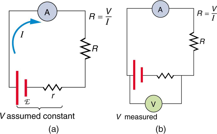
There is a variety of so-called ohmmeters that purport to measure resistance. What the most common ohmmeters actually do is to apply a voltage to a resistance, measure the current, and calculate the resistance using Ohm’s law. Their readout is this calculated resistance. Two configurations for ohmmeters using standard voltmeters and ammeters are shown in Figure 3. Such configurations are limited in accuracy, because the meters alter both the voltage applied to the resistor and the current that flows through it.
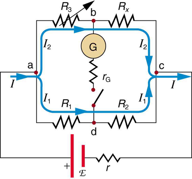
The Wheatstone bridge is a null measurement device for calculating resistance by balancing potential drops in a circuit. (See Figure 4.) The device is called a bridge because the galvanometer forms a bridge between two branches. A variety of bridge devices are used to make null measurements in circuits.
Resistors [latex]{R_1}[/latex] and [latex]{R_2}[/latex] are precisely known, while the arrow through [latex]{R_3}[/latex] indicates that it is a variable resistance. The value of [latex]{R_3}[/latex] can be precisely read. With the unknown resistance [latex]{R_{\text{x}}}[/latex] in the circuit, [latex]{R_3}[/latex] is adjusted until the galvanometer reads zero. The potential difference between points b and d is then zero, meaning that b and d are at the same potential. With no current running through the galvanometer, it has no effect on the rest of the circuit. So the branches abc and adc are in parallel, and each branch has the full voltage of the source. That is, the [latex]{IR}[/latex] drops along abc and adc are the same. Since b and d are at the same potential, the [latex]{IR}[/latex] drop along ad must equal the [latex]{IR}[/latex] drop along ab. Thus,
Again, since b and d are at the same potential, the [latex]{IR}[/latex] drop along dc must equal the [latex]{IR}[/latex] drop along bc. Thus,
Taking the ratio of these last two expressions gives
Canceling the currents and solving for Rx yields
This equation is used to calculate the unknown resistance when current through the galvanometer is zero. This method can be very accurate (often to four significant digits), but it is limited by two factors. First, it is not possible to get the current through the galvanometer to be exactly zero. Second, there are always uncertainties in [latex]{R_1}[/latex], [latex]{R_2}[/latex], and [latex]{R_3}[/latex], which contribute to the uncertainty in [latex]{R_{\text{x}}}[/latex].
Check Your Understanding
1: Identify other factors that might limit the accuracy of null measurements. Would the use of a digital device that is more sensitive than a galvanometer improve the accuracy of null measurements?
Section Summary
- Null measurement techniques achieve greater accuracy by balancing a circuit so that no current flows through the measuring device.
- One such device, for determining voltage, is a potentiometer.
- Another null measurement device, for determining resistance, is the Wheatstone bridge.
- Other physical quantities can also be measured with null measurement techniques.
Conceptual Questions
1: Why can a null measurement be more accurate than one using standard voltmeters and ammeters? What factors limit the accuracy of null measurements?
2: If a potentiometer is used to measure cell emfs on the order of a few volts, why is it most accurate for the standard [latex]\text{emf}_{\text{s}}[/latex] to be the same order of magnitude and the resistances to be in the range of a few ohms?
Problem Exercises
1: What is the [latex]\text{emf}_{\text{x}}[/latex] of a cell being measured in a potentiometer, if the standard cell’s emf is 12.0 V and the potentiometer balances for [latex]{R_{\text{x}} = 5.000 \;\Omega}[/latex] and [latex]{R_{\text{s}} = 2.500 \;\Omega}[/latex]?
2: Calculate the [latex]\text{emf}_{\text{x}}[/latex] of a dry cell for which a potentiometer is balanced when [latex]{R_{\text{x}} = 1.200 \;\Omega}[/latex], while an alkaline standard cell with an emf of 1.600 V requires [latex]{R_{\text{s}} = 1.247 \;\Omega}[/latex] to balance the potentiometer.
3: When an unknown resistance [latex]{R_{\text{x}}}[/latex] is placed in a Wheatstone bridge, it is possible to balance the bridge by adjusting [latex]{R_3}[/latex] to be [latex]{2500 \;\Omega}[/latex]. What is [latex]{R_{\text{x}}}[/latex] if [latex]{\frac{R_2}{R_1} = 0.625}[/latex]?
4: To what value must you adjust [latex]{R_3}[/latex] to balance a Wheatstone bridge, if the unknown resistance [latex]{R_{\text{x}}}[/latex] is [latex]{100 \;\Omega}[/latex], [latex]{R_1}[/latex] is [latex]{50.0 \;\Omega}[/latex], and [latex]{R_2}[/latex] is [latex]{175 \;\Omega}[/latex]?
5: (a) What is the unknown [latex]\text{emf}_{\text{x}}[/latex] in a potentiometer that balances when [latex]{R_{\text{x}}}[/latex] is [latex]{10.0 \;\Omega}[/latex], and balances when [latex]{R_{\text{s}}}[/latex] is [latex]{15.0 \;\Omega}[/latex] for a standard 3.000-V emf? (b) The same [latex]\text{emf}_{\text{x}}[/latex] is placed in the same potentiometer, which now balances when [latex]{R_{\text{s}}}[/latex] is [latex]{15.0 \;\Omega}[/latex] for a standard emf of 3.100 V. At what resistance [latex]{R_x}[/latex] will the potentiometer balance?
6: Suppose you want to measure resistances in the range from [latex]{10.0 \;\Omega}[/latex] to [latex]{10.0 \;\text{k} \Omega}[/latex] using a Wheatstone bridge that has [latex]{\frac{R_2}{R_1} = 2.000}[/latex]. Over what range should [latex]{R_3}[/latex] be adjustable?
Glossary
- null measurements
- methods of measuring current and voltage more accurately by balancing the circuit so that no current flows through the measurement device
- potentiometer
- a null measurement device for measuring potentials (voltages)
- ohmmeter
- an instrument that applies a voltage to a resistance, measures the current, calculates the resistance using Ohm’s law, and provides a readout of this calculated resistance
- bridge device
- a device that forms a bridge between two branches of a circuit; some bridge devices are used to make null measurements in circuits
- Wheatstone bridge
- a null measurement device for calculating resistance by balancing potential drops in a circuit
Solutions
Check Your Understanding
1: One factor would be resistance in the wires and connections in a null measurement. These are impossible to make zero, and they can change over time. Another factor would be temperature variations in resistance, which can be reduced but not completely eliminated by choice of material. Digital devices sensitive to smaller currents than analog devices do improve the accuracy of null measurements because they allow you to get the current closer to zero.
Problem Exercises
1: 24.0 V
3: [latex]{1.56 \;\text{k} \Omega}[/latex]
5: (a) 2.00 V
(b) [latex]{9.68 \;\Omega}[/latex]
6: [latex]{\text{Range} = 5.00 \;\Omega \;\text{to} \; 5.00 \;\text{k} \Omega}[/latex]
