Chapter 19 Electric Potential and Electric Field
19.5 Capacitors and Dielectrics
Summary
- Describe the action of a capacitor and define capacitance.
- Explain parallel plate capacitors and their capacitances.
- Discuss the process of increasing the capacitance of a dielectric.
- Determine capacitance given charge and voltage.
A capacitor is a device used to store electric charge. Capacitors have applications ranging from filtering static out of radio reception to energy storage in heart defibrillators. Typically, commercial capacitors have two conducting parts close to one another, but not touching, such as those in Figure 1. (Most of the time an insulator is used between the two plates to provide separation—see the discussion on dielectrics below.) When battery terminals are connected to an initially uncharged capacitor, equal amounts of positive and negative charge, [latex]{+Q}[/latex] and [latex]{-Q}[/latex], are separated into its two plates. The capacitor remains neutral overall, but we refer to it as storing a charge [latex]{Q}[/latex] in this circumstance.
Capacitor
A capacitor is a device used to store electric charge.
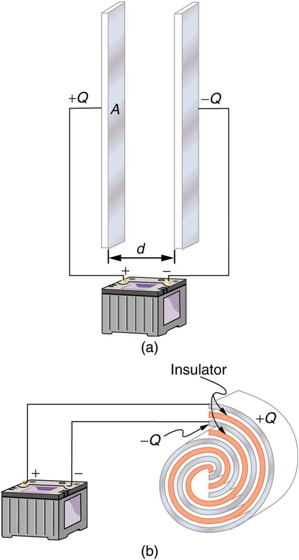
The amount of charge [latex]{Q}[/latex] a capacitor can store depends on two major factors—the voltage applied and the capacitor’s physical characteristics, such as its size.
The Amount of Charge Q a Capacitor Can Store
The amount of charge [latex]{Q}[/latex] a capacitor can store depends on two major factors—the voltage applied and the capacitor’s physical characteristics, such as its size.
A system composed of two identical, parallel conducting plates separated by a distance, as in Figure 2, is called a parallel plate capacitor. It is easy to see the relationship between the voltage and the stored charge for a parallel plate capacitor, as shown in Figure 2. Each electric field line starts on an individual positive charge and ends on a negative one, so that there will be more field lines if there is more charge. (Drawing a single field line per charge is a convenience, only. We can draw many field lines for each charge, but the total number is proportional to the number of charges.) The electric field strength is, thus, directly proportional to [latex]{Q}[/latex]
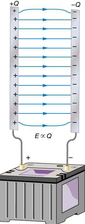
The field is proportional to the charge:
where the symbol [latex]{\propto}[/latex] means “proportional to.” From the discussion in Chapter 19.2 Electric Potential in a Uniform Electric Field, we know that the voltage across parallel plates is [latex]{V = Ed}[/latex]. Thus,
It follows, then, that [latex]{V \propto Q}[/latex], and conversely,
This is true in general: The greater the voltage applied to any capacitor, the greater the charge stored in it.
Different capacitors will store different amounts of charge for the same applied voltage, depending on their physical characteristics. We define their capacitance [latex]{C}[/latex] to be such that the charge [latex]{Q}[/latex] stored in a capacitor is proportional to [latex]{C}[/latex]. The charge stored in a capacitor is given by
This equation expresses the two major factors affecting the amount of charge stored. Those factors are the physical characteristics of the capacitor, [latex]{C}[/latex], and the voltage, VV. Rearranging the equation, we see that capacitance [latex]{C}[/latex] is the amount of charge stored per volt, or
Capacitance
Capacitance [latex]{C}[/latex] is the amount of charge stored per volt, or
The unit of capacitance is the farad (F), named for Michael Faraday (1791–1867), an English scientist who contributed to the fields of electromagnetism and electrochemistry. Since capacitance is charge per unit voltage, we see that a farad is a coulomb per volt, or
A 1-farad capacitor would be able to store 1 coulomb (a very large amount of charge) with the application of only 1 volt. One farad is, thus, a very large capacitance. Typical capacitors range from fractions of a picofarad [latex]{(1 \;\text{pF} = 10^{-12} \;\text{F})}[/latex] to millifarads [latex]{(1 \;\text{mF} = 10^{-3} \;\text{F})}[/latex].
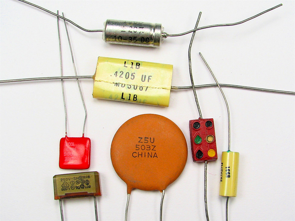
Figure 3 shows some common capacitors. Capacitors are primarily made of ceramic, glass, or plastic, depending upon purpose and size. Insulating materials, called dielectrics, are commonly used in their construction, as discussed below.
Parallel Plate Capacitor
The parallel plate capacitor shown in Figure 4 has two identical conducting plates, each having a surface area [latex]{A}[/latex], separated by a distance [latex]{d}[/latex] (with no material between the plates). When a voltage [latex]{V}[/latex] is applied to the capacitor, it stores a charge [latex]{Q}[/latex], as shown. We can see how its capacitance depends on [latex]{A}[/latex] and [latex]{d}[/latex] by considering the characteristics of the Coulomb force. We know that like charges repel, unlike charges attract, and the force between charges decreases with distance. So it seems quite reasonable that the bigger the plates are, the more charge they can store—because the charges can spread out more. Thus [latex]{C}[/latex] should be greater for larger [latex]{A}[/latex]. Similarly, the closer the plates are together, the greater the attraction of the opposite charges on them. So [latex]{C}[/latex] should be greater for smaller [latex]{d}[/latex].
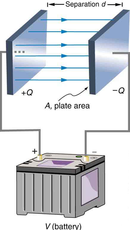
It can be shown that for a parallel plate capacitor there are only two factors ([latex]{A}[/latex] and [latex]{d}[/latex]) that affect its capacitance [latex]{C}[/latex]. The capacitance of a parallel plate capacitor in equation form is given by
Capacitance of a Parallel Plate Capacitor
[latex]{A}[/latex] is the area of one plate in square meters, and [latex]{d}[/latex] is the distance between the plates in meters. The constant [latex]{{\varepsilon}_0}[/latex] is the permittivity of free space; its numerical value in SI units is [latex]{{\varepsilon}_0 = 8.85 \times 10^{-12} \;\text{F} / \text{m}}[/latex]. The units of F/m are equivalent to [latex]{\text{C}^2 / \text{N} \cdot \text{m}^2}[/latex]. The small numerical value of [latex]{{\varepsilon}_0}[/latex] is related to the large size of the farad. A parallel plate capacitor must have a large area to have a capacitance approaching a farad. (Note that the above equation is valid when the parallel plates are separated by air or free space. When another material is placed between the plates, the equation is modified, as discussed below.)
Example 1: Capacitance and Charge Stored in a Parallel Plate Capacitor
(a) What is the capacitance of a parallel plate capacitor with metal plates, each of area [latex]{1.00 \;\text{m}^2}[/latex], separated by 1.00 mm? (b) What charge is stored in this capacitor if a voltage of [latex]{3.00 \times 10^3 \;\text{V}}[/latex] is applied to it?
Strategy
Finding the capacitance [latex]{C}[/latex] is a straightforward application of the equation [latex]{C = {\varepsilon}_0 A/d}[/latex]. Once [latex]{C}[/latex] is found, the charge stored can be found using the equation [latex]{Q = CV}[/latex].
Solution for (a)
Entering the given values into the equation for the capacitance of a parallel plate capacitor yields
Discussion for (a)
This small value for the capacitance indicates how difficult it is to make a device with a large capacitance. Special techniques help, such as using very large area thin foils placed close together.
Solution for (b)
The charge stored in any capacitor is given by the equation [latex]{Q = CV}[/latex]. Entering the known values into this equation gives
Discussion for (b)
This charge is only slightly greater than those found in typical static electricity. Since air breaks down at about [latex]{3.00 \times 10^6 \;\text{V} / \text{m}}[/latex], more charge cannot be stored on this capacitor by increasing the voltage.
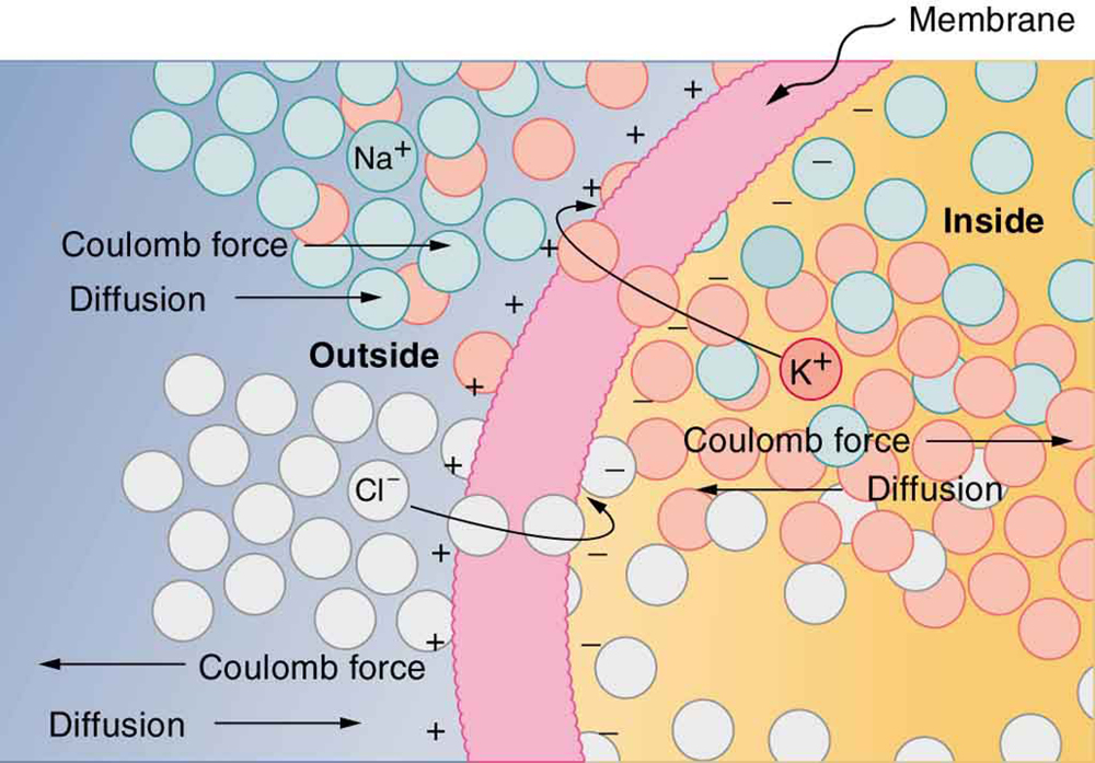
Another interesting biological example dealing with electric potential is found in the cell’s plasma membrane. The membrane sets a cell off from its surroundings and also allows ions to selectively pass in and out of the cell. There is a potential difference across the membrane of about –70 mV. This is due to the mainly negatively charged ions in the cell and the predominance of positively charged sodium (Na+) ions outside. Things change when a nerve cell is stimulated. Na+ ions are allowed to pass through the membrane into the cell, producing a positive membrane potential—the nerve signal. The cell membrane is about 7 to 10 nm thick. An approximate value of the electric field across it is given by
This electric field is enough to cause a breakdown in air.
Dielectric
The previous example highlights the difficulty of storing a large amount of charge in capacitors. If [latex]{d}[/latex] is made smaller to produce a larger capacitance, then the maximum voltage must be reduced proportionally to avoid breakdown (since [latex]{E = V/d}[/latex]). An important solution to this difficulty is to put an insulating material, called a dielectric, between the plates of a capacitor and allow [latex]{d}[/latex] to be as small as possible. Not only does the smaller [latex]{d}[/latex] make the capacitance greater, but many insulators can withstand greater electric fields than air before breaking down.
There is another benefit to using a dielectric in a capacitor. Depending on the material used, the capacitance is greater than that given by the equation [latex]{C = {\varepsilon}_0 \frac{A}{d}}[/latex] by a factor [latex]{\kappa}[/latex], called the dielectric constant. A parallel plate capacitor with a dielectric between its plates has a capacitance given by
Values of the dielectric constant [latex]{\kappa}[/latex] for various materials are given in Table 1. Note that [latex]{\kappa}[/latex] for vacuum is exactly 1, and so the above equation is valid in that case, too. If a dielectric is used, perhaps by placing Teflon between the plates of the capacitor in Example 1, then the capacitance is greater by the factor [latex]{\kappa}[/latex], which for Teflon is 2.1.
Take-Home Experiment: Building a Capacitor
How large a capacitor can you make using a chewing gum wrapper? The plates will be the aluminum foil, and the separation (dielectric) in between will be the paper.
| Material | Dielectric constant [latex]{\kappa}[/latex] | Dielectric strength (V/m) |
|---|---|---|
| Vacuum | 1.00000 | — |
| Air | 1.00059 | [latex]{3 \times 10^6}[/latex] |
| Bakelite | 4.9 | [latex]{24 \times 10^6}[/latex] |
| Fused quartz | 3.78 | [latex]{8 \times 10^6}[/latex] |
| Neoprene rubber | 6.7 | [latex]{12 \times 10^6}[/latex] |
| Nylon | 3.4 | [latex]{14 \times 10^6}[/latex] |
| Paper | 3.7 | [latex]{16 \times 10^6}[/latex] |
| Polystyrene | 2.56 | [latex]{24 \times 10^6}[/latex] |
| Pyrex glass | 5.6 | [latex]{14 \times 10^6}[/latex] |
| Silicon oil | 2.5 | [latex]{15 \times 10^6}[/latex] |
| Strontium titanate | 233 | [latex]{8 \times 10^6}[/latex] |
| Teflon | 2.1 | [latex]{60 \times 10^6}[/latex] |
| Water | 80 | — |
| Table 1. Dielectric Constants and Dielectric Strengths for Various Materials at 20ºC | ||
Note also that the dielectric constant for air is very close to 1, so that air-filled capacitors act much like those with vacuum between their plates except that the air can become conductive if the electric field strength becomes too great. (Recall that [latex]{E = V/d}[/latex] for a parallel plate capacitor.) Also shown in Table 1 are maximum electric field strengths in V/m, called dielectric strengths, for several materials. These are the fields above which the material begins to break down and conduct. The dielectric strength imposes a limit on the voltage that can be applied for a given plate separation. For instance, in Example 1, the separation is 1.00 mm, and so the voltage limit for air is
However, the limit for a 1.00 mm separation filled with Teflon is 60,000 V, since the dielectric strength of Teflon is [latex]{60 \times 10^6 \;\text{V} / \text{m}}[/latex]. So the same capacitor filled with Teflon has a greater capacitance and can be subjected to a much greater voltage. Using the capacitance we calculated in the above example for the air-filled parallel plate capacitor, we find that the Teflon-filled capacitor can store a maximum charge of
This is 42 times the charge of the same air-filled capacitor.
Dielectric Strength
The maximum electric field strength above which an insulating material begins to break down and conduct is called its dielectric strength.
Microscopically, how does a dielectric increase capacitance? Polarization of the insulator is responsible. The more easily it is polarized, the greater its dielectric constant [latex]{\kappa}[/latex]. Water, for example, is a polar molecule because one end of the molecule has a slight positive charge and the other end has a slight negative charge. The polarity of water causes it to have a relatively large dielectric constant of 80. The effect of polarization can be best explained in terms of the characteristics of the Coulomb force. Figure 5 shows the separation of charge schematically in the molecules of a dielectric material placed between the charged plates of a capacitor. The Coulomb force between the closest ends of the molecules and the charge on the plates is attractive and very strong, since they are very close together. This attracts more charge onto the plates than if the space were empty and the opposite charges were a distance [latex]{d}[/latex] away.
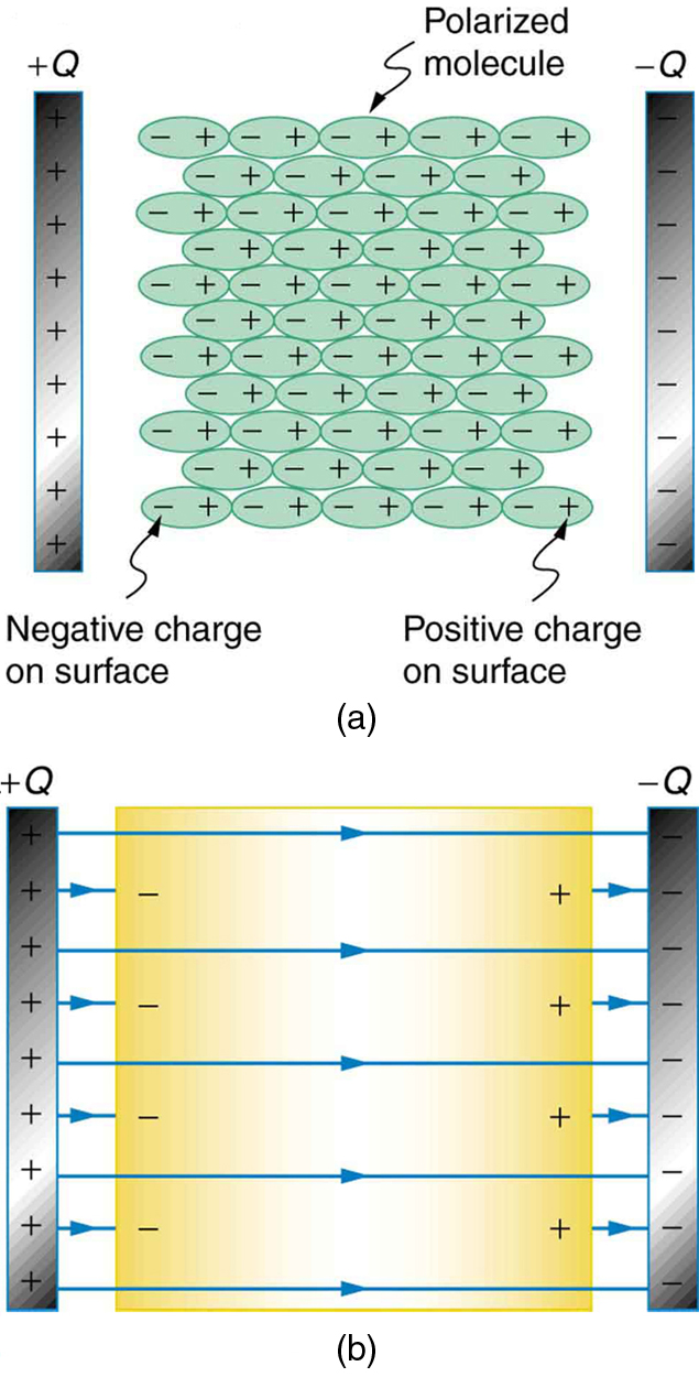
Another way to understand how a dielectric increases capacitance is to consider its effect on the electric field inside the capacitor. Figure 5(b) shows the electric field lines with a dielectric in place. Since the field lines end on charges in the dielectric, there are fewer of them going from one side of the capacitor to the other. So the electric field strength is less than if there were a vacuum between the plates, even though the same charge is on the plates. The voltage between the plates is [latex]{V = Ed}[/latex], so it too is reduced by the dielectric. Thus there is a smaller voltage [latex]{V}[/latex] for the same charge [latex]{Q}[/latex]; since [latex]{C = Q/V}[/latex], the capacitance [latex]{C}[/latex] is greater.
The dielectric constant is generally defined to be [latex]{\kappa = E_0/E}[/latex], or the ratio of the electric field in a vacuum to that in the dielectric material, and is intimately related to the polarizability of the material.
Things Great and Small
The Submicroscopic Origin of Polarization
Polarization is a separation of charge within an atom or molecule. As has been noted, the planetary model of the atom pictures it as having a positive nucleus orbited by negative electrons, analogous to the planets orbiting the Sun. Although this model is not completely accurate, it is very helpful in explaining a vast range of phenomena and will be refined elsewhere, such as in Chapter 30 Atomic Physics. The submicroscopic origin of polarization can be modeled as shown in Figure 6.
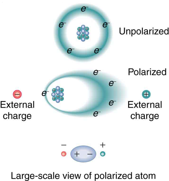
We will find in Chapter 30 Atomic Physics that the orbits of electrons are more properly viewed as electron clouds with the density of the cloud related to the probability of finding an electron in that location (as opposed to the definite locations and paths of planets in their orbits around the Sun). This cloud is shifted by the Coulomb force so that the atom on average has a separation of charge. Although the atom remains neutral, it can now be the source of a Coulomb force, since a charge brought near the atom will be closer to one type of charge than the other.
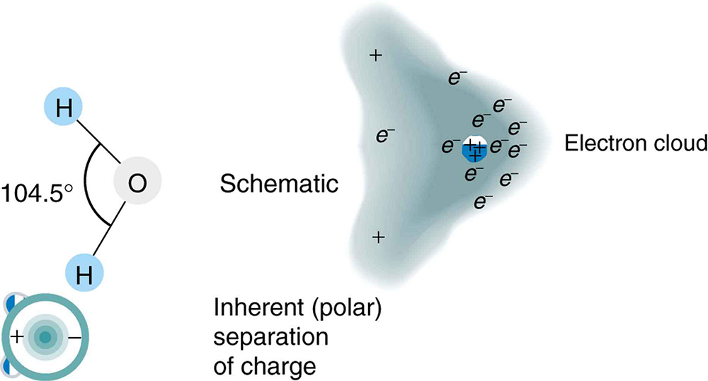
Some molecules, such as those of water, have an inherent separation of charge and are thus called polar molecules. Figure 7 illustrates the separation of charge in a water molecule, which has two hydrogen atoms and one oxygen atom [latex]{\text{H}_2 \text{O}}[/latex]. The water molecule is not symmetric—the hydrogen atoms are repelled to one side, giving the molecule a boomerang shape. The electrons in a water molecule are more concentrated around the more highly charged oxygen nucleus than around the hydrogen nuclei. This makes the oxygen end of the molecule slightly negative and leaves the hydrogen ends slightly positive. The inherent separation of charge in polar molecules makes it easier to align them with external fields and charges. Polar molecules therefore exhibit greater polarization effects and have greater dielectric constants. Those who study chemistry will find that the polar nature of water has many effects. For example, water molecules gather ions much more effectively because they have an electric field and a separation of charge to attract charges of both signs. Also, as brought out in the previous chapter, polar water provides a shield or screening of the electric fields in the highly charged molecules of interest in biological systems.
PhET Explorations: Capacitor Lab
Explore how a capacitor works! Change the size of the plates and add a dielectric to see the effect on capacitance. Change the voltage and see charges built up on the plates. Observe the electric field in the capacitor. Measure the voltage and the electric field.

Section Summary
- A capacitor is a device used to store charge.
- The amount of charge [latex]{Q}[/latex] a capacitor can store depends on two major factors—the voltage applied and the capacitor’s physical characteristics, such as its size.
- The capacitance [latex]{C}[/latex] is the amount of charge stored per volt, or
[latex]{C =}[/latex] [latex]{\frac{Q}{V}}.[/latex]
- The capacitance of a parallel plate capacitor is [latex]{C ={\varepsilon}_0}{\frac{A}{d}}[/latex], when the plates are separated by air or free space. [latex]{{\varepsilon}_0}[/latex] is called the permittivity of free space.
- A parallel plate capacitor with a dielectric between its plates has a capacitance given by
[latex]{C = \kappa {\varepsilon}_0}[/latex] [latex]{\frac{A}{d}} ,[/latex]
where [latex]{\kappa}[/latex] is the dielectric constant of the material.
- The maximum electric field strength above which an insulating material begins to break down and conduct is called dielectric strength.
Conceptual Questions
1: Does the capacitance of a device depend on the applied voltage? What about the charge stored in it?
2: Use the characteristics of the Coulomb force to explain why capacitance should be proportional to the plate area of a capacitor. Similarly, explain why capacitance should be inversely proportional to the separation between plates.
3: Give the reason why a dielectric material increases capacitance compared with what it would be with air between the plates of a capacitor. What is the independent reason that a dielectric material also allows a greater voltage to be applied to a capacitor? (The dielectric thus increases [latex]{C}[/latex] and permits a greater [latex]{V}[/latex].)
4: How does the polar character of water molecules help to explain water’s relatively large dielectric constant? (Figure 7)
5: Sparks will occur between the plates of an air-filled capacitor at lower voltage when the air is humid than when dry. Explain why, considering the polar character of water molecules.
6: Water has a large dielectric constant, but it is rarely used in capacitors. Explain why.
7: Membranes in living cells, including those in humans, are characterized by a separation of charge across the membrane. Effectively, the membranes are thus charged capacitors with important functions related to the potential difference across the membrane. Is energy required to separate these charges in living membranes and, if so, is its source the metabolization of food energy or some other source?
Problems & Exercises
1: What charge is stored in a [latex]{180 \;\mu \text{F}}[/latex] capacitor when 120 V is applied to it?
2: Find the charge stored when 5.50 V is applied to an 8.00 pF capacitor.
3: What charge is stored in the capacitor in Example 1?
4: Calculate the voltage applied to a [latex]{2 .00 \;\mu \text{F}}[/latex] capacitor when it holds [latex]{3.10 \;\mu \text{C}}[/latex] of charge.
5: What voltage must be applied to an 8.00 nF capacitor to store 0.160 mC of charge?
6: What capacitance is needed to store [latex]{3.00 \;\mu \text{C}}[/latex] of charge at a voltage of 120 V?
7: What is the capacitance of a large Van de Graaff generator’s terminal, given that it stores 8.00 mC of charge at a voltage of 12.0 MV?
8: Find the capacitance of a parallel plate capacitor having plates of area [latex]{5.00 \;\text{m}^2}[/latex] that are separated by 0.100 mm of Teflon.
9: (a)What is the capacitance of a parallel plate capacitor having plates of area [latex]{1.50 \;\text{m}^2}[/latex] that are separated by 0.0200 mm of neoprene rubber? (b) What charge does it hold when 9.00 V is applied to it?
10: Integrated Concepts
A prankster applies 450 V to an [latex]{80.0 \;\mu \text{F}}[/latex] capacitor and then tosses it to an unsuspecting victim. The victim’s finger is burned by the discharge of the capacitor through 0.200 g of flesh. What is the temperature increase of the flesh? Is it reasonable to assume no phase change?
11: Unreasonable Results
(a) A certain parallel plate capacitor has plates of area [latex]{4.00 \;\text{m}^2}[/latex], separated by 0.0100 mm of nylon, and stores 0.170 C of charge. What is the applied voltage? (b) What is unreasonable about this result? (c) Which assumptions are responsible or inconsistent?
Glossary
- capacitor
- a device that stores electric charge
- capacitance
- amount of charge stored per unit volt
- dielectric
- an insulating material
- dielectric strength
- the maximum electric field above which an insulating material begins to break down and conduct
- parallel plate capacitor
- two identical conducting plates separated by a distance
- polar molecule
- a molecule with inherent separation of charge
Solutions
Problems & Exercises
1: [latex]{21.6 \;\text{mC}}[/latex]
3: [latex]{80.0 \;\text{mC}}[/latex]
5: 20.0 kV
7: [latex]{667 \;\text{pF}}[/latex]
9: (a) [latex]{4.4 \;\mu \text{F}}[/latex]
(b) [latex]{4.0 \times 10^{-5} \;\text{C}}[/latex]
11: (a) 14.2 kV
(b) The voltage is unreasonably large, more than 100 times the breakdown voltage of nylon.
(c) The assumed charge is unreasonably large and cannot be stored in a capacitor of these dimensions.

