Chapter 4 The Second Law of Thermodynamics
4.3 Refrigerators and Heat Pumps
OpenStax and Paula Herrera-Siklody
Learning Objectives
By the end of this section, you will be able to:
- Describe a refrigerator and a heat pump and list their differences
- Calculate the performance coefficients of simple refrigerators and heat pumps
The cycles we used to describe the engine in the preceding section are all reversible, so each sequence of steps can just as easily be performed in the opposite direction. In this case, the engine is known as a refrigerator or a heat pump, depending on what is the focus: the heat removed from the cold reservoir or the heat dumped to the hot reservoir. Either a refrigerator or a heat pump is an engine running in reverse. For a refrigerator, the focus is on removing heat from a specific area. For a heat pump, the focus is on dumping heat to a specific area.
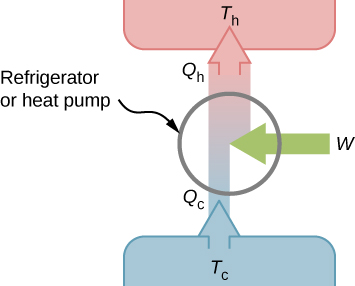
We first consider a refrigerator (Figure 4.6). The purpose of this engine is to remove heat from the cold reservoir, which is the space inside the refrigerator for an actual household refrigerator or the space inside a building for an air-conditioning unit.

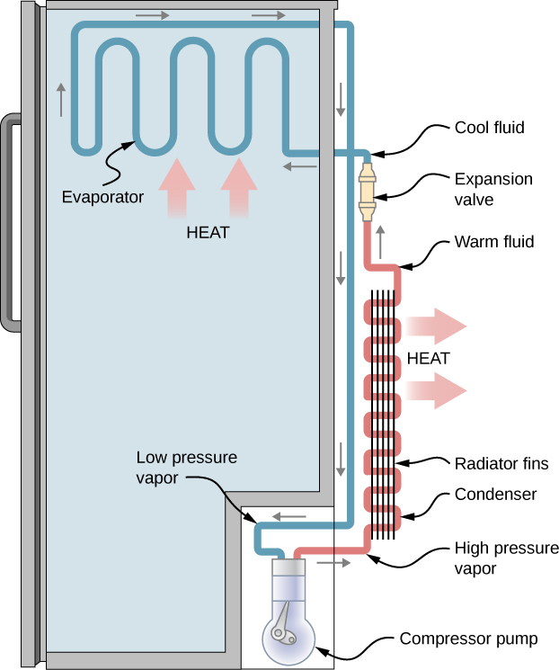
A refrigerator (or heat pump) absorbs heat [latex]Q_\text{c}[/latex] from the cold reservoir at Kelvin temperature [latex]T_\text{c}[/latex] and discards heat [latex]Q_\text{h}[/latex] to the hot reservoir at Kelvin temperature [latex]T_\text{h}[/latex], while work W is done on the engine’s working substance, as shown by the arrow pointing toward the system in the figure. A household refrigerator removes heat from the food within it while exhausting heat to the surrounding air. The required work, for which we pay in our electricity bill, is performed by the motor that moves a coolant through the coils. A schematic sketch of a household refrigerator is given in Figure 4.7.

The effectiveness or coefficient of performance [latex]K_\text{R}[/latex] of a refrigerator is measured by the heat removed from the cold reservoir divided by the work done by the working substance cycle by cycle:
Note that we have used the condition of energy conservation, [latex]W = Q_\text{h} - Q_\text{c}[/latex], in the final step of this expression.The effectiveness or coefficient of performance [latex]K_\text{P}[/latex] of a heat pump is measured by the heat dumped to the hot reservoir divided by the work done to the engine on the working substance cycle by cycle:
Once again, we use the energy conservation condition [latex]W = Q_\text{h} - Q_\text{c}[/latex] to obtain the final step of this expression.
Media Attributions
- Figure 4.6
- Figure 4.7

