
Chapter 4 Dynamics: Force and Newton’s Laws of Motion
4.7 Further Applications of Newton’s Laws of Motion
Summary
- Apply problem-solving techniques to solve for quantities in more complex systems of forces.
- Integrate concepts from kinematics to solve problems using Newton’s laws of motion.
There are many interesting applications of Newton’s laws of motion, a few more of which are presented in this section. These serve also to illustrate some further subtleties of physics and to help build problem-solving skills.
Example 1: Drag Force on a Barge
Suppose two tugboats push on a barge at different angles, as shown in Figure 1. The first tugboat exerts a force of [latex]{2.7\times10^5\text{ N}}[/latex] in the x-direction, and the second tugboat exerts a force of [latex]{3.6\times10^5\text{ N}}[/latex] in the y-direction.
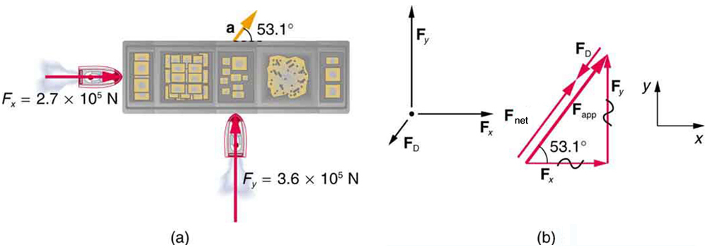
If the mass of the barge is [latex]{5.0\times10^6\text{ kg}}[/latex] and its acceleration is observed to be [latex]{7.5\times10^{-2}\text{ m/s}^2}[/latex] in the direction shown, what is the drag force of the water on the barge resisting the motion? (Note: drag force is a frictional force exerted by fluids, such as air or water. The drag force opposes the motion of the object.)
Strategy
The directions and magnitudes of acceleration and the applied forces are given in Figure 1(a). We will define the total force of the tugboats on the barge as [latex]\textbf{F}_{\text{app}}[/latex] so that:
Since the barge is flat bottomed, the drag of the water [latex]\textbf{F}_{\textbf{D}}[/latex] will be in the direction opposite to [latex]\textbf{F}_{\text{app}},[/latex] as shown in the free-body diagram in Figure 1(b). The system of interest here is the barge, since the forces on it are given as well as its acceleration. Our strategy is to find the magnitude and direction of the net applied force [latex]\textbf{F}_{\text{app}},[/latex] and then apply Newton’s second law to solve for the drag force [latex]\textbf{F}_{\textbf{D}}.[/latex]
Solution
Since [latex]{\textbf{F}_x}[/latex] and [latex]{\textbf{F}_y}[/latex] are perpendicular, the magnitude and direction of [latex]\textbf{F}_{\text{app}}[/latex] are easily found. First, the resultant magnitude is given by the Pythagorean theorem:
The angle is given by
which we know, because of Newton’s first law, is the same direction as the acceleration. [latex]\textbf{F}_{\textbf{D}}[/latex] is in the opposite direction of [latex]\textbf{F}_{\text{app}},[/latex] since it acts to slow down the acceleration. Therefore, the net external force is in the same direction as [latex]\textbf{F}_{\text{app}},[/latex] but its magnitude is slightly less than [latex]\textbf{F}_{\text{app}}.[/latex] The problem is now one-dimensional. From Figure 1(b), we can see that
But Newton’s second law states that
Thus,
This can be solved for the magnitude of the drag force of the water [latex]{F_{\textbf{D}}}[/latex] in terms of known quantities:
Substituting known values gives
The direction of [latex]\textbf{F}_{\textbf{D}}[/latex] has already been determined to be in the direction opposite to [latex]\textbf{F}_{\text{app}},[/latex] or at an angle of [latex]{53^{\circ}}[/latex] south of west.
Discussion
The numbers used in this example are reasonable for a moderately large barge. It is certainly difficult to obtain larger accelerations with tugboats, and small speeds are desirable to avoid running the barge into the docks. Drag is relatively small for a well-designed hull at low speeds, consistent with the answer to this example, where [latex]{F_{\textbf{D}}}[/latex] is less than 1/600th of the weight of the ship.
In the earlier example of a tightrope walker we noted that the tensions in wires supporting a mass were equal only because the angles on either side were equal. Consider the following example, where the angles are not equal; slightly more trigonometry is involved.
Example 2: Different Tensions at Different Angles
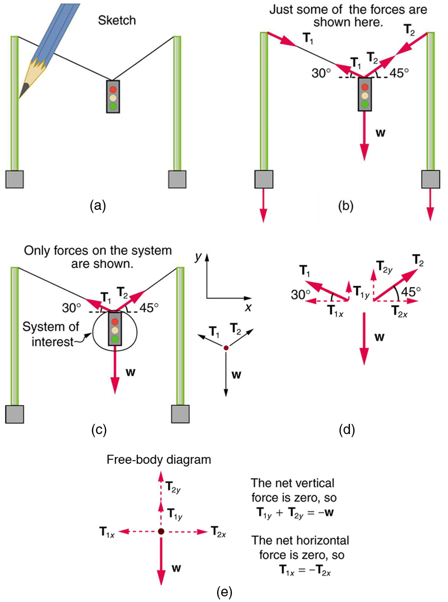
Consider the traffic light (mass 15.0 kg) suspended from two wires as shown in Figure 2. Find the tension in each wire, neglecting the masses of the wires.
Strategy
The system of interest is the traffic light, and its free-body diagram is shown in Figure 2(c). The three forces involved are not parallel, and so they must be projected onto a coordinate system. The most convenient coordinate system has one axis vertical and one horizontal, and the vector projections on it are shown in part (d) of the figure. There are two unknowns in this problem ( [latex]{T_1}[/latex] and [latex]{T_2}[/latex] ), so two equations are needed to find them. These two equations come from applying Newton’s second law along the vertical and horizontal axes, noting that the net external force is zero along each axis because acceleration is zero.
Solution
First consider the horizontal or x-axis:
Thus, as you might expect,
This gives us the following relationship between [latex]{T_1}[/latex] and [latex]{T_2}:[/latex]
Thus,
Note that [latex]{T_1}[/latex] and [latex]{T_2}[/latex] are not equal in this case, because the angles on either side are not equal. It is reasonable that [latex]{T_2}[/latex] ends up being greater than [latex]{T_1},[/latex] because it is exerted more vertically than [latex]{T_1}.[/latex]
Now consider the force components along the vertical or y-axis:
This implies
Substituting the expressions for the vertical components gives
There are two unknowns in this equation, but substituting the expression for [latex]{T_2}[/latex] in terms of [latex]{T_1}[/latex] reduces this to one equation with one unknown:
which yields
Solving this last equation gives the magnitude of [latex]{T_1}[/latex] to be
Finally, the magnitude of [latex]{T_2}[/latex] is determined using the relationship between them, [latex]{T_2}[/latex] = 1.225 [latex]{T_1},[/latex] found above. Thus we obtain
Discussion
Both tensions would be larger if both wires were more horizontal, and they will be equal if and only if the angles on either side are the same (as they were in the earlier example of a tightrope walker).
The bathroom scale is an excellent example of a normal force acting on a body. It provides a quantitative reading of how much it must push upward to support the weight of an object. But can you predict what you would see on the dial of a bathroom scale if you stood on it during an elevator ride? Will you see a value greater than your weight when the elevator starts up? What about when the elevator moves upward at a constant speed: will the scale still read more than your weight at rest? Consider the following example.
Example 3: What Does the Bathroom Scale Read in an Elevator?
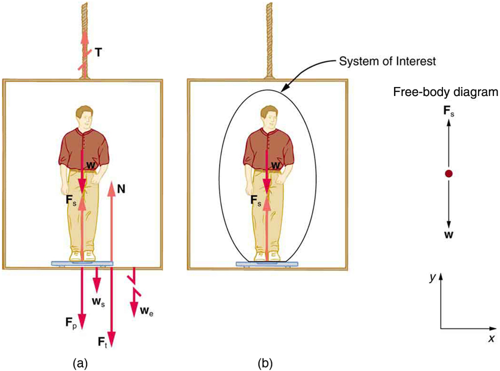
Figure 3 shows a 75.0-kg man (weight of about 165 lb) standing on a bathroom scale in an elevator. Calculate the scale reading: (a) if the elevator accelerates upward at a rate of [latex]{1.20\text{ m/s}^2}[/latex] , and (b) if the elevator moves upward at a constant speed of 1 m/s.
Strategy
If the scale is accurate, its reading will equal [latex]{F_{\textbf{p}}},[/latex] the magnitude of the force the person exerts downward on it. Figure 3(a) shows the numerous forces acting on the elevator, scale, and person. It makes this one-dimensional problem look much more formidable than if the person is chosen to be the system of interest and a free-body diagram is drawn as in Figure 3(b). Analysis of the free-body diagram using Newton’s laws can produce answers to both parts (a) and (b) of this example, as well as some other questions that might arise. The only forces acting on the person are his weight [latex]\textbf{w}[/latex] and the upward force of the scale [latex]\textbf{F}_{\text{s}}.[/latex] According to Newton’s third law [latex]\textbf{F}_{\textbf{p}}[/latex] and [latex]\textbf{F}_{\text{s}}[/latex] are equal in magnitude and opposite in direction, so that we need to find [latex]{F_{\text{s}}}[/latex] in order to find what the scale reads. We can do this, as usual, by applying Newton’s second law,
From the free-body diagram we see that [latex]{F_{\text{net}}=F_{\text{s}}-w},[/latex] so that
Solving for [latex]{F_{\text{s}}}[/latex] gives an equation with only one unknown:
or, because [latex]{w=mg},[/latex] simply
No assumptions were made about the acceleration, and so this solution should be valid for a variety of accelerations in addition to the ones in this exercise.
Solution for (a)
In this part of the problem, [latex]{a=1.20\text{ m/s}^2},[/latex] so that
yielding
Discussion for (a)
This is about 185 lb. What would the scale have read if he were stationary? Since his acceleration would be zero, the force of the scale would be equal to his weight:
So, the scale reading in the elevator is greater than his 735-N (165 lb) weight. This means that the scale is pushing up on the person with a force greater than his weight, as it must in order to accelerate him upward. Clearly, the greater the acceleration of the elevator, the greater the scale reading, consistent with what you feel in rapidly accelerating versus slowly accelerating elevators.
Solution for (b)
Now, what happens when the elevator reaches a constant upward velocity? Will the scale still read more than his weight? For any constant velocity—up, down, or stationary—acceleration is zero because [latex]{a=\frac{\Delta{v}}{\Delta{t}}},[/latex] and [latex]{\Delta{v}=0}.[/latex]
Thus,
Now
which gives
Discussion for (b)
The scale reading is 735 N, which equals the person’s weight. This will be the case whenever the elevator has a constant velocity—moving up, moving down, or stationary.
The solution to the previous example also applies to an elevator accelerating downward, as mentioned. When an elevator accelerates downward, [latex]{a}[/latex] is negative, and the scale reading is less than the weight of the person, until a constant downward velocity is reached, at which time the scale reading again becomes equal to the person’s weight. If the elevator is in free-fall and accelerating downward at [latex]{g},[/latex] then the scale reading will be zero and the person will appear to be weightless.
Integrating Concepts: Newton’s Laws of Motion and Kinematics
Physics is most interesting and most powerful when applied to general situations that involve more than a narrow set of physical principles. Newton’s laws of motion can also be integrated with other concepts that have been discussed previously in this text to solve problems of motion. For example, forces produce accelerations, a topic of kinematics, and hence the relevance of earlier chapters. When approaching problems that involve various types of forces, acceleration, velocity, and/or position, use the following steps to approach the problem:
Problem-Solving Strategy
Step 1. Identify which physical principles are involved. Listing the givens and the quantities to be calculated will allow you to identify the principles involved.
Step 2. Solve the problem using strategies outlined in the text. If these are available for the specific topic, you should refer to them. You should also refer to the sections of the text that deal with a particular topic. The following worked example illustrates how these strategies are applied to an integrated concept problem.
Example 4: What Force Must a Soccer Player Exert to Reach Top Speed?
A soccer player starts from rest and accelerates forward, reaching a velocity of 8.00 m/s in 2.50 s. (a) What was his average acceleration? (b) What average force did he exert backward on the ground to achieve this acceleration? The player’s mass is 70.0 kg, and air resistance is negligible.
Strategy
- To solve an integrated concept problem, we must first identify the physical principles involved and identify the chapters in which they are found. Part (a) of this example considers acceleration along a straight line. This is a topic of kinematics. Part (b) deals with force, a topic of dynamics found in this chapter.
- The following solutions to each part of the example illustrate how the specific problem-solving strategies are applied. These involve identifying knowns and unknowns, checking to see if the answer is reasonable, and so forth.
Solution for (a)
We are given the initial and final velocities (zero and 8.00 m/s forward); thus, the change in velocity is [latex]{\Delta{v}=8.00\text{ m/s}}.[/latex] We are given the elapsed time, and so [latex]{\Delta{t}=2.50\text{ s}}.[/latex] The unknown is acceleration, which can be found from its definition:
Substituting the known values yields
Discussion for (a)
This is an attainable acceleration for an athlete in good condition.
Solution for (b)
Here we are asked to find the average force the player exerts backward to achieve this forward acceleration. Neglecting air resistance, this would be equal in magnitude to the net external force on the player, since this force causes his acceleration. Since we now know the player’s acceleration and are given his mass, we can use Newton’s second law to find the force exerted. That is,
Substituting the known values of [latex]{m}[/latex] and [latex]{a}[/latex] gives
Discussion for (b)
This is about 50 pounds, a reasonable average force.
This worked example illustrates how to apply problem-solving strategies to situations that include topics from different chapters. The first step is to identify the physical principles involved in the problem. The second step is to solve for the unknown using familiar problem-solving strategies. These strategies are found throughout the text, and many worked examples show how to use them for single topics. You will find these techniques for integrated concept problems useful in applications of physics outside of a physics course, such as in your profession, in other science disciplines, and in everyday life. The following problems will build your skills in the broad application of physical principles.
Summary
- Newton’s laws of motion can be applied in numerous situations to solve problems of motion.
- Some problems will contain multiple force vectors acting in different directions on an object. Be sure to draw diagrams, resolve all force vectors into horizontal and vertical components, and draw a free-body diagram. Always analyze the direction in which an object accelerates so that you can determine whether [latex]{F_{\text{net}}=ma}[/latex] or [latex]{F_{\text{net}}=0}.[/latex]
- The normal force on an object is not always equal in magnitude to the weight of the object. If an object is accelerating, the normal force will be less than or greater than the weight of the object. Also, if the object is on an inclined plane, the normal force will always be less than the full weight of the object.
- Some problems will contain various physical quantities, such as forces, acceleration, velocity, or position. You can apply concepts from kinematics and dynamics in order to solve these problems of motion.
Conceptual Questions
1: To simulate the apparent weightlessness of space orbit, astronauts are trained in the hold of a cargo aircraft that is accelerating downward at [latex]{g}.[/latex] Why will they appear to be weightless, as measured by standing on a bathroom scale, in this accelerated frame of reference? Is there any difference between their apparent weightlessness in orbit and in the aircraft?
2: A cartoon shows the toupee coming off the head of an elevator passenger when the elevator rapidly stops during an upward ride. Can this really happen without the person being tied to the floor of the elevator? Explain your answer.
Problems & Exercises
1: A flea jumps by exerting a force of [latex]{1.20\times10^{-5}\text{ N}}[/latex] straight down on the ground. A breeze blowing on the flea parallel to the ground exerts a force of [latex]{0.500\times10^{-6}\text{ N}}[/latex] on the flea. Find the direction and magnitude of the acceleration of the flea if its mass is [latex]{6.00\times10^{-7}\text{ kg}}.[/latex] Do not neglect the gravitational force.
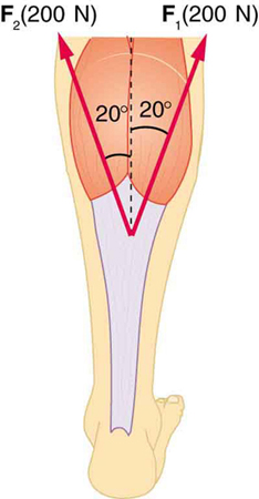
2: Two muscles in the back of the leg pull upward on the Achilles tendon, as shown in Figure 4. (These muscles are called the medial and lateral heads of the gastrocnemius muscle.) Find the magnitude and direction of the total force on the Achilles tendon. What type of movement could be caused by this force?
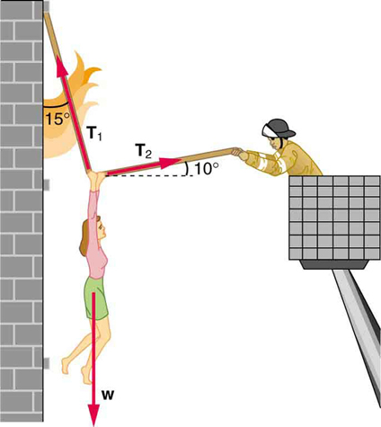
3: A 76.0-kg person is being pulled away from a burning building as shown in Figure 5. Calculate the tension in the two ropes if the person is momentarily motionless. Include a free-body diagram in your solution.
4: Integrated Concepts A 35.0-kg dolphin decelerates from 12.0 to 7.50 m/s in 2.30 s to join another dolphin in play. What average force was exerted to slow him if he was moving horizontally? (The gravitational force is balanced by the buoyant force of the water.)
5: Integrated Concepts When starting a foot race, a 70.0-kg sprinter exerts an average force of 650 N backward on the ground for 0.800 s. (a) What is his final speed? (b) How far does he travel?
6: Integrated Concepts A large rocket has a mass of [latex]{2.00\times10^6\text{ kg}}[/latex] at takeoff, and its engines produce a thrust of [latex]{3.50\times10^7\text{ N}}.[/latex] (a) Find its initial acceleration if it takes off vertically. (b) How long does it take to reach a velocity of 120 km/h straight up, assuming constant mass and thrust? (c) In reality, the mass of a rocket decreases significantly as its fuel is consumed. Describe qualitatively how this affects the acceleration and time for this motion.
7: Integrated Concepts A basketball player jumps straight up for a ball. To do this, he lowers his body 0.300 m and then accelerates through this distance by forcefully straightening his legs. This player leaves the floor with a vertical velocity sufficient to carry him 0.900 m above the floor. (a) Calculate his velocity when he leaves the floor. (b) Calculate his acceleration while he is straightening his legs. He goes from zero to the velocity found in part (a) in a distance of 0.300 m. (c) Calculate the force he exerts on the floor to do this, given that his mass is 110 kg.
8: Integrated Concepts A 2.50-kg fireworks shell is fired straight up from a mortar and reaches a height of 110 m. (a) Neglecting air resistance (a poor assumption, but we will make it for this example), calculate the shell’s velocity when it leaves the mortar. (b) The mortar itself is a tube 0.450 m long. Calculate the average acceleration of the shell in the tube as it goes from zero to the velocity found in (a). (c) What is the average force on the shell in the mortar? Express your answer in newtons and as a ratio to the weight of the shell.
9: Integrated Concepts Repeat Exercise 8 for a shell fired at an angle [latex]{10.0^{\circ}}[/latex] from the vertical.
10: Integrated Concepts An elevator filled with passengers has a mass of 1700 kg. (a) The elevator accelerates upward from rest at a rate of [latex]{1.20\text{ m/s}^2}[/latex] for 1.50 s. Calculate the tension in the cable supporting the elevator. (b) The elevator continues upward at constant velocity for 8.50 s. What is the tension in the cable during this time? (c) The elevator decelerates at a rate of [latex]{0.600\text{ m/s}^2}[/latex] for 3.00 s. What is the tension in the cable during deceleration? (d) How high has the elevator moved above its original starting point, and what is its final velocity?
11: Unreasonable Results (a) What is the final velocity of a car originally traveling at 50.0 km/h that decelerates at a rate of [latex]{0.400\text{ m/s}^2}[/latex] for 50.0 s? (b) What is unreasonable about the result? (c) Which premise is unreasonable, or which premises are inconsistent?
12: Unreasonable Results A 75.0-kg man stands on a bathroom scale in an elevator that accelerates from rest to 30.0 m/s in 2.00 s. (a) Calculate the scale reading in newtons and compare it with his weight. (The scale exerts an upward force on him equal to its reading.) (b) What is unreasonable about the result? (c) Which premise is unreasonable, or which premises are inconsistent?
Solutions
Problems & Exercises
1:
[latex]{10.2\text{ m/s}^2, 4.67^{\circ}\text{ from vertical}}[/latex]
3:
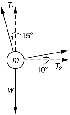
[latex]{T_1=736\text{ N}}[/latex]
[latex]{T_2=194\text{ N}}[/latex]
5:
(a) [latex]{7.43\text{ m/s}}[/latex]
(b) 2.97 m
7:
(a) [latex]{4.20\text{ m/s}}[/latex]
(b) [latex]{29.4\text{ m/s}^2}[/latex]
(c) [latex]{4.31\times10^3\text{ N}}[/latex]
9:
(a) 47.1 m/s
(b) [latex]{2.47\times10^3\text{ m/s}^2}[/latex]
(c) [latex]{6.18\times10^3\text{ N}}.[/latex] The average force is 252 times the shell’s weight.
