Chapter 23 Electromagnetic Induction, AC Circuits, and Electrical Technologies
23.4 Eddy Currents and Magnetic Damping
Summary
- Explain the magnitude and direction of an induced eddy current, and the effect this will have on the object it is induced in.
- Describe several applications of magnetic damping.
Eddy Currents and Magnetic Damping
As discussed in Chapter 23.3 Motional Emf, motional emf is induced when a conductor moves in a magnetic field or when a magnetic field moves relative to a conductor. If motional emf can cause a current loop in the conductor, we refer to that current as an eddy current. Eddy currents can produce significant drag, called magnetic damping, on the motion involved. Consider the apparatus shown in Figure 1, which swings a pendulum bob between the poles of a strong magnet. (This is another favorite physics lab activity.) If the bob is metal, there is significant drag on the bob as it enters and leaves the field, quickly damping the motion. If, however, the bob is a slotted metal plate, as shown in Figure 1(b), there is a much smaller effect due to the magnet. There is no discernible effect on a bob made of an insulator. Why is there drag in both directions, and are there any uses for magnetic drag?
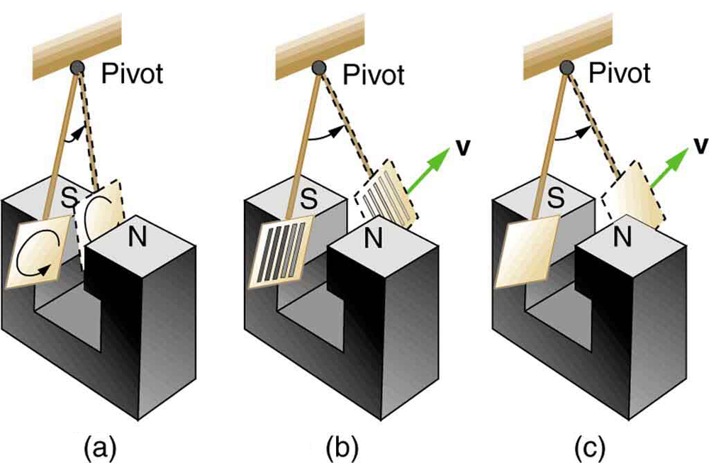
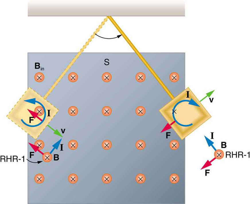
Figure 2 shows what happens to the metal plate as it enters and leaves the magnetic field. In both cases, it experiences a force opposing its motion. As it enters from the left, flux increases, and so an eddy current is set up (Faraday’s law) in the counterclockwise direction (Lenz’s law), as shown. Only the right-hand side of the current loop is in the field, so that there is an unopposed force on it to the left (RHR-1). When the metal plate is completely inside the field, there is no eddy current if the field is uniform, since the flux remains constant in this region. But when the plate leaves the field on the right, flux decreases, causing an eddy current in the clockwise direction that, again, experiences a force to the left, further slowing the motion. A similar analysis of what happens when the plate swings from the right toward the left shows that its motion is also damped when entering and leaving the field.
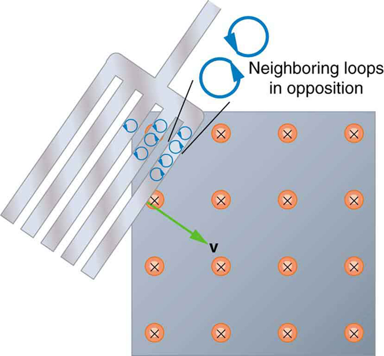
When a slotted metal plate enters the field, as shown in Figure 3, an emf is induced by the change in flux, but it is less effective because the slots limit the size of the current loops. Moreover, adjacent loops have currents in opposite directions, and their effects cancel. When an insulating material is used, the eddy current is extremely small, and so magnetic damping on insulators is negligible. If eddy currents are to be avoided in conductors, then they can be slotted or constructed of thin layers of conducting material separated by insulating sheets.
Applications of Magnetic Damping
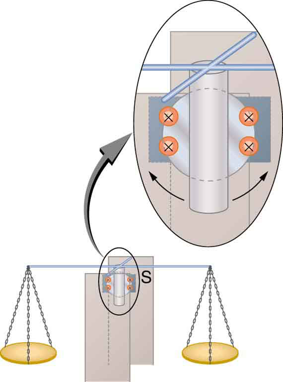
One use of magnetic damping is found in sensitive laboratory balances. To have maximum sensitivity and accuracy, the balance must be as friction-free as possible. But if it is friction-free, then it will oscillate for a very long time. Magnetic damping is a simple and ideal solution. With magnetic damping, drag is proportional to speed and becomes zero at zero velocity. Thus the oscillations are quickly damped, after which the damping force disappears, allowing the balance to be very sensitive. (See Figure 4.) In most balances, magnetic damping is accomplished with a conducting disc that rotates in a fixed field.
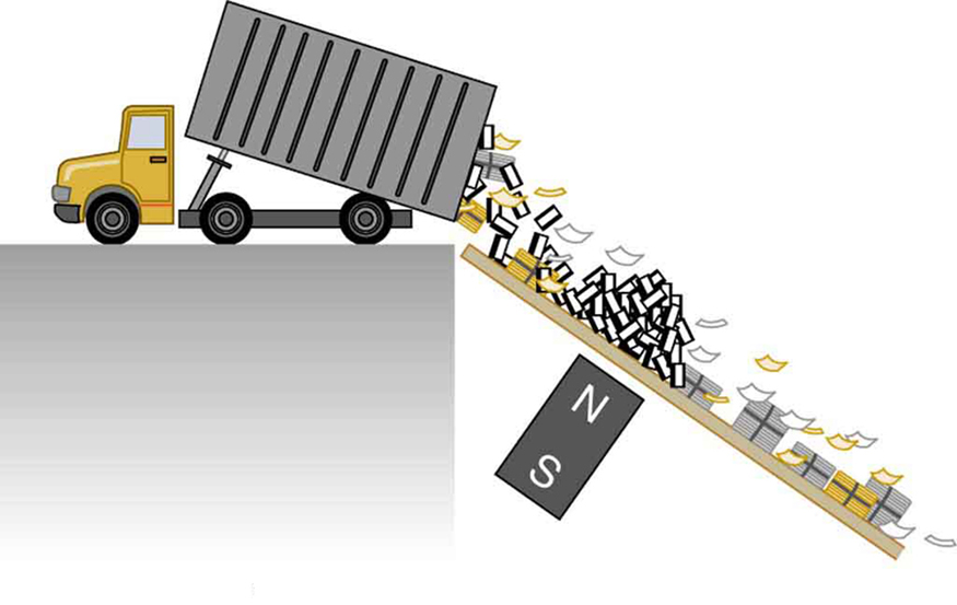
Since eddy currents and magnetic damping occur only in conductors, recycling centers can use magnets to separate metals from other materials. Trash is dumped in batches down a ramp, beneath which lies a powerful magnet. Conductors in the trash are slowed by magnetic damping while nonmetals in the trash move on, separating from the metals. (See Figure 5.) This works for all metals, not just ferromagnetic ones. A magnet can separate out the ferromagnetic materials alone by acting on stationary trash.
Other major applications of eddy currents are in metal detectors and braking systems in trains and roller coasters. Portable metal detectors (Figure 6) consist of a primary coil carrying an alternating current and a secondary coil in which a current is induced. An eddy current will be induced in a piece of metal close to the detector which will cause a change in the induced current within the secondary coil, leading to some sort of signal like a shrill noise. Braking using eddy currents is safer because factors such as rain do not affect the braking and the braking is smoother. However, eddy currents cannot bring the motion to a complete stop, since the force produced decreases with speed. Thus, speed can be reduced from say 20 m/s to 5 m/s, but another form of braking is needed to completely stop the vehicle. Generally, powerful rare earth magnets such as neodymium magnets are used in roller coasters. Figure 7 shows rows of magnets in such an application. The vehicle has metal fins (normally containing copper) which pass through the magnetic field slowing the vehicle down in much the same way as with the pendulum bob shown in Figure 1.
![]Photograph of several soldiers in an open field. One soldier is searching for explosives by scanning the surface using a metal detector.](https://pressbooks.online.ucf.edu/app/uploads/sites/96/2019/08/Figure_24_04_06.jpg)

Induction cooktops have electromagnets under their surface. The magnetic field is varied rapidly producing eddy currents in the base of the pot, causing the pot and its contents to increase in temperature. Induction cooktops have high efficiencies and good response times but the base of the pot needs to be ferromagnetic, iron or steel for induction to work.
Section Summary
- Current loops induced in moving conductors are called eddy currents.
- They can create significant drag, called magnetic damping.
Conceptual Questions
1: Explain why magnetic damping might not be effective on an object made of several thin conducting layers separated by insulation.
2: Explain how electromagnetic induction can be used to detect metals? This technique is particularly important in detecting buried landmines for disposal, geophysical prospecting and at airports.
Problems & Exercises
1: Make a drawing similar to Figure 2, but with the pendulum moving in the opposite direction. Then use Faraday’s law, Lenz’s law, and RHR-1 to show that magnetic force opposes motion.

2: A coil is moved through a magnetic field as shown in Figure 8. The field is uniform inside the rectangle and zero outside. What is the direction of the induced current and what is the direction of the magnetic force on the coil at each position shown?
Glossary
- eddy current
- a current loop in a conductor caused by motional emf
- magnetic damping
- the drag produced by eddy currents

