
1 Chapter 1: Control Volume Analysis
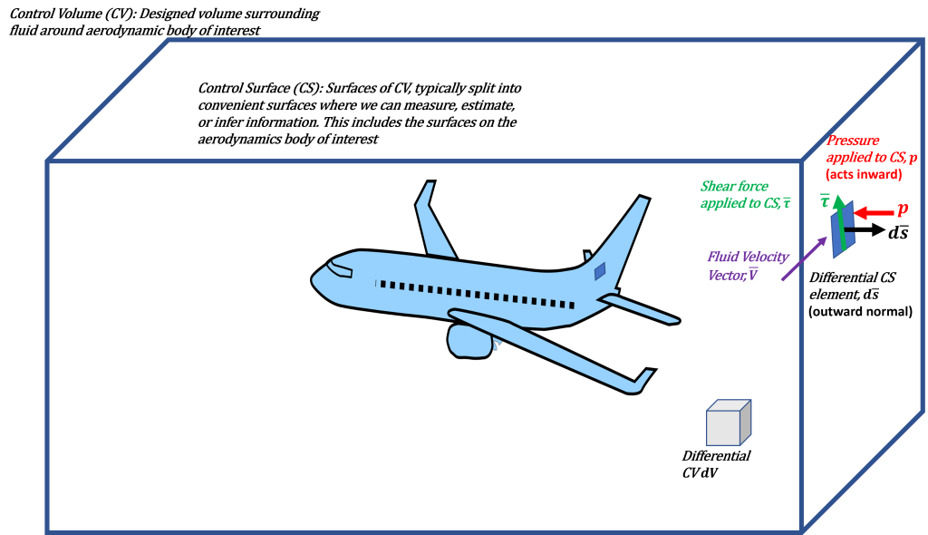
In fluid dynamics, a control volume (CV) is the Free Body Diagram (FBD) equivalent to establishing a flow analysis. A generic CV is displayed in Fig. 1.1. CVs are volumes that define where the fluid is to be assessed. Hence, the fluids analyses are to be evaluated within the control volume and on the surfaces of the control volume (control surfaces, CS). On the CS’s, we track fluid motion and properties in and out of the CV. The resulting implication is that these are surfaces that we track transport of fluid and underlying properties (such as mass, momentum, and energy) moving through the system (or CV).
CV’s are critical not only to establish conservation equations for fluid dynamics, but also for understanding aerodynamics systems and closing out aerodynamic principles. Let’s consider various conservation laws for fluids (in the context of continuum assumptions). These laws are developed in the context of the Reynolds Transport Theorem and are formulated to ensure that various fluid quantities s are conserved. In the context of gas, we often assume no “body forces.” Body forces would include forces such as gravity (which is of less importance in air, but is important for hydrodynamics), or other underlying body forces would include magnetohydrodynamics, but do not need further discussion.
Reynolds Transport Theorem combined with three basic conservation principles enables the formation of the governing equations of fluid dynamics. The principles are specifically that mass is conserved, Newton’s 2nd law (resulting in momentum conservation), and the 1st law of thermodynamics (energy is conserved). Using these principles, we can formulate the governing equations for fluid dynamics.
Let us first consider Conservation of Mass. The essence of this conservation law is that mass is neither created nor destroyed. In the context of an Eulerian CV analysis, Conservation of Mass states that within the CV mass will buildup based on the net flux into and out of the system. The equation is given as follows:
(1) 
Here,  is density,
  is the volume,
  is the fluid velocity vector, and
  is the differential element on the control surface with an outward-normal direction. The left term indicates the aforementioned buildup within a control volume. Referring back to Figure 1.1, the
  term is an individual volume element that when multiplied by the density provides a differential mass. Hence, the integral is the total mass in the system. When we take the time derivative,
  , we are evaluating how the total mass in the system changes. The second term indicates the net flux out of the CV. and this is evaluated on the CS, that is, where mass can move in or out to the system. Flux implies stuff moving through the CS and is specifically given on a differential level by
  . When multiplied by , it becomes a mass flux. As indicated in Figure 1.1., term is a local, surface normal vector. The magnitude is the area of the differential element (
 ). The orientation (or vector) aspect aligns it to be outward surface normal with a normal unit vector of
  . Hence,
  which yields a differential element of the CS with an outward-normal orientation. Lastly, it is important to note that in this conventional form, the outward normal direction to implies that the flux out of the CV is positive. Hence, always note that fluxes, by convention, are positive when stuff moves out and negative coming in.
Important notes about the conservation of mass:
- Almost always important
- Used to provide mass flow rates through systems
- Always ensure this relation is satisfied when solving the conservation of momentum and energy
- Mass flux is positive moving out of the CV, negative coming in
Let’s now move to formulate the Conservation of Momentum. This conservation law implies that momentum is conserved and is the Eulerian representation of  . In dynamics, is specified in a Lagrangian reference frame, while in fluids and aerodynamics, it is convenient to work in the Eulerian reference frame (established through Reynolds Transport Theorem). The essence of the Conservation of Momentum is to related momentum deficits and/or rises on CSs and use this to infer internal aerodynamic forces on the body (such as lift/drag/thrust). Conservation of Momentum is given as
(2) 
Here, we now consider  as the pressure and
  as the shear forces acting on the CS. The left-hand side (LHS) of the equation includes the time-rate-of-change of momentum in the CV and the net momentum flux out of the CV. In the context of , the LHS can be interpreted as the
  term. Specifically,
  is the time-rate of change of momentum within the CV, while
  is the momentum flux out of the CV. Similar to Conservation of Mass, the momentum flux out of the CV is positive.
Now consider the right-hand side (RHS) of the conservation of momentum (Eq.2). In the context of , this is  . Consider this as forces applied to CSs of the CV. In aerodynamics the forces are driven by integrating pressure and viscous forces on all the CSs. Consider spliting the CS into subsurfaces. In Figure 1.1, for example, we have outer boundaries where flow comes in and out and surfaces on the aircraft which have no flux. For each of these surfaces, we need pressure and viscous forces. For the outer boundaries, this information can be difficult, hence, we normally design the CV to avoid this. On the aerodynamic body CS, the integration of these pressure and viscous forces directly relates to aerodynamics. More specifically, these terms are the force of the body acting on the fluid in the CV, while the aerodynamic forces are reaction forces from the fluid. Hence, these CS integrals on aerodynamic bodies are critical.
When addresses this force terms, keep in mind that they also have direction. Here, pressure acts into the CV (i.e., from outside the CV to inside) and has direction associated with the . This yields the negative sign and force given by  . A similar notion is implied for the viscous force.
 , obtained along a streamline.
Important notes about the conservation of momentum:
- Important when obtaining forces
- Used to understand/infer loads on bodies in a system
- Always ensure you solve this with the conservation of mass
- This equation does not explicitly have losses (yet it can provide drag).
- Although momentum flux is positive outward. Forces are considered being applied to the CS (pressure acts normal from the outward and and shear is computed on the CS). Keep this convention for assigning the signs.
- Forms the origin of Bernoulli Equation (applied to a stream tube)
Example 1: Reaction force from in a pipe flow through an elbow using mass and momentum equations.
Example 2: Inferring the drag on an airfoil from a wake measurement using mass and momentum equations. Note the importance of conserving mass.
Now let us consider the conservation of energy, which is often ignored in aerodynamics, however, its principle is critical as it relates to losses. Conservation of energy implies that energy is conserved in the context of Eulerian analyses with the foundational being driven by the 1st law of thermodynamics. Hence, it states that the rate-of-change of energy is equal to the heat added minus the work extracted, or  . An important factor here is that we need to consider the total energy as the sum of the internal energy (
 ) and kinetic energy (
 ). The energy is therefore defined as
  . Overall, the conservation of energy equation balances the time-rate-of-change in energy as a result of imbalances associated with net energy flux out of the system along with heat and work applied to the system. In addition, we must also include the losses (such as viscous losses), work applied to the fluid (such as propellers), and internally generated energy (such as energy released from combustion).
The energy equation in an Eulerian reference frame is given as
(4) 
Here, we now consider  as the heat exchange processes and
  as the work performed on the fluid system from the aerodynamic forces (ie., propellers act as a pump and add work, drag would alternatively extract work).
The LHS of equation 6 includes the time-rate-of-change of energy associated with the mass within the CV combined with the net energy flux out of the CV. In the context of , the LHS can be interpreted as the  term.
term.
Now lefts move to the RHS of the equation, which includes the heat and work added to the system. The heat term is given by
(5) 
Physically, these are be represented by heat generated within the system ( ) and heat flux into the system (
 ). Note that convention here is heat flux into the CV is positive (i.e., heat flux increases the energy in the CV).
The aerodynamic work occurs through the flow work ( ) and viscous work (
 ). In the context of aerodynamics, the work terms are directly driven by CS are applied along bodies of interest, and arise from the flow and viscous works. Note that the viscous work term typically contains the losses associated with drag. Often, you also neglect these control surfaces and represent the aerodynamic work as follows:
(6) 
Hence, a wing or propeller can be considered to add/remove work to the CV without direct integration.
 , or losses due to viscous effects or flow separation,
  energy extraction from a turbine) or head rise (
 , energy rises from a pump) occurs. The result is as follows
 , , , and
  (a kinetic energy correction factor) accounts for energy in non-uniform profiles. These equations drive our understanding of pipe-flow analyses. This is not normally important for aerodynamics, however, in the context of V/STOL that relies on redirecting flow streams, this is an important concept to recall. For example, a deflected jet system with high values of will be very inefficient.
Important notes about the conservation of energy:
- Important when temperatures change or high-speed flow (
 )
)
- Quantifies temperature, density, energy input, and heat transfer in a system
- Always ensure you solve this with the conservation of mass
- Fluid-associated losses live in this equation
- Headloss relationships associated with piping networks are derived from this equation applied to a stream tube
Example 3: Assessing the aerodynamics of a propeller using mass, momentum, and energy equations
Key Skills: Consider these as you work through homework.
- Given a wake downstream of an airfoil, calculate the drag.
- Given a drag on an airfoil, calculate the the momentum in the wake.
- Given an aircraft with a drag force of D and a propeller thrust T, describe how the net axial momentum flux on a CV surrounding the aircraft will be when: (a) T=D, (b) T>D, and (c) T<D.
- Understand the connection between downwash, lift, and the governing equations. Know which equations to use and how.