
Main Body
Chapter 5, Angular momentum: the object that is behind itself

“Star Trails over Mount Bromo, Indonesia” by Hui Chieh is licensed under CC BY-NC 2.0
In chapter 2, on states of motion, we examined Aristotle’s idea that an arrow continues its flight through the air because the air continuously loops behind the arrow and continuously pushed the arrow forward. One of the many counters to Aristotle’s idea of air pushing a projectile from behind is the circular disk. Any object with rotational symmetry about one of its axes, like a child’s top or a millstone, once set to spinning with a bit of push, cannot stay in motion, according to Aristotle, because there is no air behind any part of that object. Air might surround it, but any kilogram, gram or molecule in motion has another molecule, gram or kilogram of matter directly behind it, not air. It is behind itself.
And, of course, the child’s top spins, the millstone spins and, if its bearing is good, without much friction at its point of contact, it will continue to spin for a good while. That being the case, it is logical to ask a few questions about this spin motion. What we shall find is that spin, and angular motion in general, gives us a point of leverage into the quantum world of photons and electrons, nuclei, atoms and molecules

U
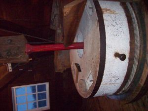
“Millstone Revealed”by Zoesdare is licensed under CC BY-NC 2.0
How does one get leverage on an object?

“D7K_1551” by Brightworks School is licensed under CC BY-NC-ND 2.0
A lever exerts your force on another object with a curious multiplier effect, leverage. That is, if you are a small human being, you can move a mountain, if your lever is long enough. This is what the great mathematician Archimedes said, “Give me a lever and a place to stand, and I will move the entire world.”
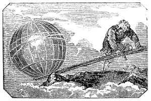

Had Archimedes a see-saw in his backyard,he might have explained it in this way: “At equal positions, my son defeats his little sister, because he is heavier. But my little daughter can defeat her brother and leave him stranded up in the air if she gets farther out. To prevent tantrums, however, I will instruct my son to scoot in to the place at which his little sister exactly balances him, even Stephen, then they can go with me for some cannoli — I’m getting hungry!” For instance, if Archimedes’ six-year old son has a mass of 20 kg, weight force of 196 N, and his 4-year old daughter has a mass of 15 kg, weight force of 147 N, then the three states correspond to these three diagrams on a 4.00 m see saw:
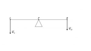
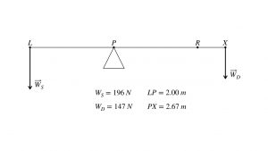
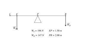
From these three examples, you can see that the multiplier is the distance from the pivot. That is, with additional distance, the daughter’s weight can match or overbalance the weight of the son. This means that the relevant dynamical quantity is the product of force and distance from the pivot. This product is also known as the torque.
There is one fine point about torque to keep in mind, however. The angle at which you apply the force to a lever is important.
 and
and  .
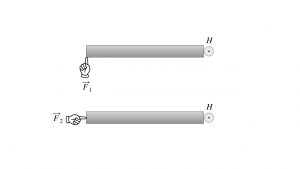
.Think of the ways you can open a door, and think of flailing, how to push on a door making it impossible to actually open it. To open a door, you push perpendicular to the surface of the door, as in the fingertip pushing the door with force . With the hinge at point H, the door will open clockwise. However, if you push like the second fingertip, with force directed toward the hinge, you are flailing. The door will not open.
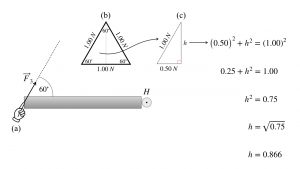
Another example draws out the primary geometric factor affecting torque. Think of the same door, but now you push with a 1.00 N force at an angle of 60 degrees, as shown. Force  makes a 60 degree angle with the door. The force contains a bit of force toward point H, the hinge, and some force perpendicular to the door.
 at an angle of
  . (b) The force triangle is one half of an equilateral triangle. (c) Working with the Pythagorean theorem on the force triangle, the amount of force back toward the hinge, parallel (||) to the door, is
  and the force perpendicular to the door is
  .
.So for every 1.00 N you exert at 60 degrees, the effective force perpendicular to the door is 0.866 N. The other component, 0.50 N toward the hinge, is wasted effort.
You may view this effective component,  , of the applied force,
  , as
, as
- being perpendicular to the door, or
- in general, perpendicular to the line between the point of application, A, and the center of the rotational motion, C, or
- you may view it as being tangent to the arc of rotational motion through point A.
The view that effective force  is tangent to the arc is consonant with the idea of work being done by a force tangent to the path. However, an engineer, who actually designs the door or the rotating piece of equipment, will tend to view the effective force as being perpendicular to the segment AC. Both views are perfectly acceptable.
Where is the center of mass of an irregularly shaped object?
Another important idea for an object that is rotating is its center of mass. The center of mass is the precise point about which each gram of mass balances another gram of mass on the opposite side of the center of mass point. For a regular shape, it is usually at the center if the object is all the same material: all steel, all wood, all polypropylene etc. For example, a plastic domino’s center of mass is easy to determine — it’s the exact center and halfway through the thickness, as shown in this diagram.
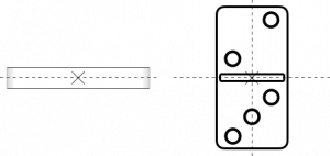
You could balance the domino on your fingertip if you place your fingertip right underneath that center point.
However, an irregularly shaped object like a wrench from a toolbox, without much symmetry, if any, will have a center of mass location off center. In this photo, the student’s finger is underneath the irregularly shaped ratchet, but not at the center.

It is closer to the heavier end, on the left, where there is more steel. This is similar to the “even Stephen” see-saw example.
For instance, in the diagram below, the ratchet has a center of mass off center, at point C. The actual ratchet measures 195 mm, from L to R, but from L to C measures in at 78 mm. This means the distance from C to R is 117 mm.
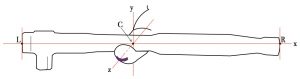
The ratio of distances is not 3:4 as in the see-saw “even Stephen” example; 78:117 reduces to 2:3. Where the center of mass lies along a given axis, 2:3 or 3:4 or some other ratio, depends on the distribution of mass along the axis. For the ratchet, the end on the left has the ratchet head, a lot of additional steel. So, the center of mass has to be a bit closer to the left end than it is to the right end.
Does the center of mass have any effect on the spinning motion of an object like domino or a wrench?
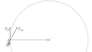
An object not fixed to an axle or hinge will rotate about its center of mass if a force is applied at some distance from the center of mass. Think of a small wooden board floating quietly on the surface of a pond, no alligators nearby.
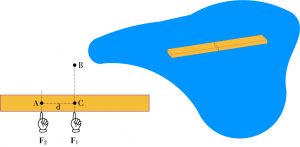
If you poke the board with a stick, it will cause some acceleration away from the stick, and if off center, the poke will cause the stick to spin, as well. That is, in the overhead view of the above diagram, a poke in the direction of , directed through the center of mass C, will only accelerate the board straight upward, toward point B. However, a poke in the same direction, parallel to , but at a distance d to the left, and directed toward point A, will cause the board to accelerate in the same upward direction and cause it to spin clockwise about the center of mass at C.
This is a complex motion, spinning as well as translating. It is one of the reasons that astronauts working in space, outside the space shuttle or the space station, must be very careful of the forces they apply to the equipment. Because of Newton’s third law, they, themselves, or their equipment, or both, can go flying off into space, spinning, a true disaster.
If an extended object can spin as well as translate, and if the translational momentum is the coin of the realm in Newton’s second law, then is there a rotational analogue to translational momentum we need to study?

The dynamical quantity that interacting objects can exchange, which is a constant of the system if no external, unbalanced forces cause more spin: it does exist. That dynamical quantity is called angular momentum. In the olden days of Jacob Bernoulli and Leonhard Euler, they used the term, “moment of momentum,” but angular momentum is less awkward, and we use that expression today. Angular momentum is a cousin of regular linear momentum, or translational momentum, but it encodes one more thing to be of interest for spinning objects: it encodes the distribution of mass. For instance, it should make common sense to you that a 45 cm wide 5 kg dumbbell should be easier to spin about its center of mass than a 45 cm wide 10 kg dumbbell would be. That is, hang each dumbbell by a string attached to the center of the bar, as shown, 5 kg dumbbell on the left, 10 kg dumbbell on the right.
The larger 10 kg dumbbell will be harder to spin in the counterclockwise manner of the curved red arrow. That is because the 10 kg dumbbell has more mass out there, 22.5 cm from the center of the bar.
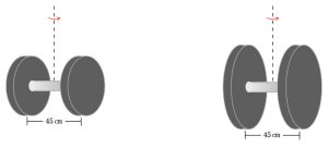
Take a look at another variation: same mass but different arrangement of that mass. The diagram below shows a 5 kg dumbbell, 45 cm across, on the left, and, for comparison, a 5 kg dumbbell with extra extension to 60 cm.
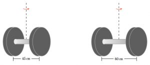
The two dumbbells have the same mass but the extended dumbbell on the right will be harder to rotate counterclockwise, in the manner of the curved red arrow. It is equally easy to lift either 5 kg dumbbell upward — you just need 49 N of upward force for that task. But it is harder to rotate the extended 5 kg dumbbell because its mass is further away from the spin axis: 30 cm out, compared to 22.5 cm out for the regular 5 kg dumbbell.
Therefore, there is a rotational quantity that encodes the distribution of mass and expresses the resistance to change in the rotational state, to changes in angular momentum. That rotational quantity is called the moment of inertia. The moment of inertia must therefore take into account the grams or kilograms of mass of the object, and the distance from the spin axis of each gram of mass. It does not matter which side of the spin axis that gram or kilogram is. In terms of the dumbbell, 2.5 kg on the right side of the dumbbell has the same effect, rotationally, as 2.5 kg on the left side of the dumbbell. So this rotational quantity, moment of inertia, will not be a vector quantity. That, in turn, means the distance will appear in the formula as the square of the distance from the spin axis.
Let’s idealize the dumbbell and use the idealized view to get a formula for moment of inertia. Instead of two flat cylinders of iron at each end of a relatively light but strong bar, let’s idealize the dumbbell to two points of mass  at each end of a rigid bar with negligible mass, at points P and Q in the diagram, so that we can focus on (1) the mass, gram by gram, out at each end and on (2) the distance r of points P and Q from the center point C. For simplicity, let’s use the spin axis placed at the center of the rigid bar, and we will call it the y-axis.
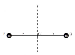
This idealization is called a “rigid rotator,” a model used extensively in quantum physics and chemistry. The contribution to the moment of inertia from the mass at point P is simply  , the product of the mass with the square of the distance. The mass at point Q also contributes . So the total moment of inertia
  of the rigid rotator is
![\[I=2mr^2\]](https://pressbooks.online.ucf.edu/app/uploads/quicklatex/quicklatex.com-7d39ad490a3c25f7b46f244889066ab8_l3.png "Rendered by QuickLaTeX.com")
Another simple example is a hoop, which is simply a set of rigid rotators of the same radius angled out into a circle. Here is an overhead view, with the  symbol to represent the spin axis coming out of the page, and with a curved red arrow to give an example of a counterclockwise spin sense.
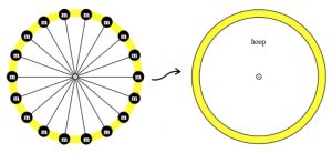
It is a set of nine rigid rotators but not yet a hoop. Can you see where we are going? To go from rigid rotators to a hoop, think of a set of very small pixels of mass in the form of rigid rotators, but many of them, partnered up continuously with other rigid rotator pixels of mass all the way around into a circle. As the pixels get smaller and smaller, the nine rigid rotators become eighteen then thirty-six and so on, ad infinitum, gradually becoming a smooth object, the hoop. In the diagram below, for comparison, the yellow hoop lies below the set of nine rigid rotators.
The moment of inertia for this simple system is just  multiplied by the entire mass of the hoop, because each gram of the mass is at a distance
  from the spin axis! If the mass of the hoop is
  , then the moment of inertia about the spin axis is
![\[I=Mr^2\]](https://pressbooks.online.ucf.edu/app/uploads/quicklatex/quicklatex.com-908b66c852a305658f2a9476aee19440_l3.png "Rendered by QuickLaTeX.com")
.
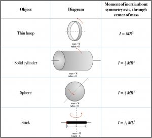
Usually, the moment of inertia of a symmetrical object relative to a spin axis through its center of mass is a small integer or a simple fraction multiplied by the object’s total mass and the square of some representative distance, like the radius of a wheel or the length of the edge of a cube. The following table gives moment of inertia relative to the spin axis on the symmetry line drawn through the center of mass, for our hoop, a solid cylinder, a sphere and a straight rod or stick.
With moment of inertia, the rotational analog of mass, we can now get to angular momentum. Translational or linear momentum is the product of mass and velocity. Our formula for angular momentum will therefore be the product of moment of inertia and angular velocity, symbolized  . One RPM of angular speed is 360 degrees per minute, 6 degrees per second. Alternatively, we can use the radian system, based on one full circle of 360 degrees being equivalent to 2π. So
  is the same as
  , which is about
  . In the radian system, we do not use a symbol for the radian — it is understood as radians from the context. At long last, here is the formula for angular momentum,
  , of an object whose moment of is , turning at rate :
![\[L=I\omega\]](https://pressbooks.online.ucf.edu/app/uploads/quicklatex/quicklatex.com-3f6c9f3036068f4fd5537510c102eaf7_l3.png "Rendered by QuickLaTeX.com")
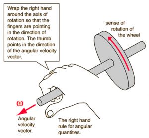
The angular momentum is a vector quantity. The formula above gives its size, and the right hand rule gives its direction. In the metric system, its units are  . Usually angular momentum points along the spin axis, according to the right hand rule.
 , and for angular momentum,
  . Image: HyperPhysics (©C.R. Nave, 2017)
In addition, the formula for kinetic energy of spinning motion is very similar to  for a regular object. Specifically,
![\[KE_{spinning}=\frac{1}{2}I \omega^2\]](https://pressbooks.online.ucf.edu/app/uploads/quicklatex/quicklatex.com-1845ba022f8221c12f3aa0bb1a78e9b1_l3.png "Rendered by QuickLaTeX.com")
In the table of simple figures and their moments of inertia, the angular momentum of the hoop and that of the cylinder point to the left, the angular momentum of the sphere points up, to the right and slightly toward you, and the angular momentum of the stick points straight up the page.
In the figure below, you can view a pair of oppositely rotating discs with their angular momentum vector sketched in. The top row shows the overhead view of a yellow disc spinning counterclockwise, displaying its angular momentum vector with the ⊙ symbol. It is aimed up out of the plane of the page.
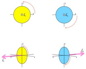 , when viewed from above; the blue disk spins clockwise
  . When viewed in perspective, the yellow disk’s angular momentum vector
  points leftward along the positive z-axis, but the blue disk’s angular momentum vector
  points rightward along the negative z-axis.
The blue disc spins clockwise, and the diagram represents its angular momentum vector with the ⊗ symbol. This symbol means that the vector’s arrow is heading away from you, straight into the plane of the page. The bottom row shows a perspective view of each disc, with its angular momentum vector sketched in as a pink arrow.
.
Is angular momentum conserved?
An extended object,
- if spinning, and
- if there are no external torques,
will tend to resist changes to its angular momentum state because it has a moment of inertia. It can preserve its angular momentum state even though internal forces might rearrange the distribution of matter. You might have seen a figure skater in the Olympics, spinning in place with her arms or legs extended.

The ice is smooth, the blades of the skates are smooth, and of low friction, so the skate/ice interaction provides no significant external torque on the skater. When the skater pulls in her limbs, however, her spin rate increases dramatically.
I always refer to this as the “ice skater effect.” The ice skater has rearranged several kilograms of her body’s limbs:
- from extension at large values of ,
- to the pulled in position, much smaller values of .
Extending and pulling in her limbs requires some  muscle force, but they are her muscle forces, hence internal forces. These forces decrease and for each gram of body mass that has pulled in, so the sum of all the , her moment of inertia, is smaller. If the angular momentum is to stay constant, then the angular velocity must increase. She spins up: the ice skater effect.
![\[\vec{L}=I\vec{\omega} \longrightarrow \vec{\omega}=\frac{\vec{L}}{I}\]](https://pressbooks.online.ucf.edu/app/uploads/quicklatex/quicklatex.com-e8a6723e63ff5ac7ea9cc025487b4542_l3.png "Rendered by QuickLaTeX.com")
When the denominator becomes smaller, the overall quotient gets larger. Thus, increases.
The UCF courses I have taught over the years include demonstrations of the ice skater effect, using hand weights and a rotating lab stool… plus brave students! You can view digital videos of angular momentum demonstrations in our YouTube area, e.g.,
Enjoy!
Conservation of angular momentum requires that even the direction of is conserved. A simple example is the gyroscope.
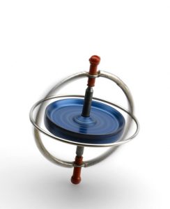
The gyroscope will keep its spin axis and angular momentum vector pointing in one direction, no matter how you may try to let it tip over. We can also ascribe the stability of a bicycle to the angular momentum state of its spinning wheels.
Aircraft and spacecraft have inertial guidance systems in addition to the Global Positioning System (GPS), and the early inertial guidance systems used spinning gyroscopes. A gyroscope on low friction bearings, forever pointing at the North Star, for example, provides a stable reference system that allows one to measure the tilting, torquing accelerations on the aircraft. As F.K. Mueller wrote, in his brief history of inertial guidance systems[1], “Measurement of accelerations is the key to inertial guidance.” With those measurements, a computer must then compute a zillion distance rectangles and distance triangles very rapidly, thereby making an estimate of the aircraft position above the surface of Earth.
There is a famous international incident, the Korean Airlines Flight 007 shootdown in 1983, which many people attribute to an error in the gyroscopic inertial guidance system of the Boeing 747 aircraft. On its flight to Seoul, South Korea, from Anchorage, Alaska, the aircraft’s inertial guidance computed position frequently but inaccurately, telling the pilots that they were in the normal air traffic corridor over the North Pacific. In reality, they had strayed over Soviet Union, crossing the Kamchatka Peninsula and then Sakhalin Island. Soviet fighter aircraft fired air-to-air missiles at the airliner. Just west of Sakhalin Island and a hundred miles or so north to the Japanese island of Hokkaido, the 747 jumbo jet crashed into the sea, killing everyone aboard.
Electrons behave like tiny gyroscopes. We have detected no internal structure to the electron, no “anatomy,” so they cannot rearrange themselves like an ice skater can do. However electrons do interact with their own angular momentum states. Scientists have observed very fine differences in the electrodynamics of hydrogen and other atoms, because an electron has two types of angular momentum: its intrinsic spin angular momentum, and its orbital angular momentum from its orbital motion around the nucleus. It is beyond the scope of this book to get into the details of the spin/orbit interaction, but there are plenty of other everyday systems we can observe in which objects interact and exchange angular momenta.
How do objects interact and exchange angular momenta?
If you have observed the classroom demonstration with the spinning bicycle wheel, or the video of it, then you have watched momentum being exchanged under conditions where, like the ice skater, angular momentum is conserved. The only forces acting are the “internal” forces of the student, exerting some Newtons to flip the bicycle wheel, up side down. But the initial angular momentum of the system, student on the stool + bicycle wheel is all in the wheel,
![\[\vec{L}_{total,\: i}=\vec{L}_{wheel}\]](https://pressbooks.online.ucf.edu/app/uploads/quicklatex/quicklatex.com-e9ec717608a46b50c9481212f4b7be4e_l3.png "Rendered by QuickLaTeX.com")
because the student initially is at rest:  .
.
Note that, in the video above, this initial angular momentum for the wheel is downward. We could write it as a negative number of  .
.
After the student flips the wheel, the total angular momentum must again be  , but both the wheel and the student on the stool are spinning. The video shows that the sense of the student’s spin is clockwise, so the student-on-stool angular momentum is downward.
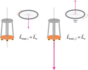
The wheel, meanwhile, is flipped, so its angular momentum is  , opposite its initial angular momentum. This means that the student/stool angular momentum must be
  , twice the wheel’s initial angular momentum. That being the case, the total final angular momentum is
![\[\vec{L}_{total,\: f}=2\vec{L}_{wheel}-\vec{L}_{wheel}=\vec{L}_{wheel}=\vec{L}_{total, \: i}\]](https://pressbooks.online.ucf.edu/app/uploads/quicklatex/quicklatex.com-1669303bafb0b8e02a9ca9ffc61c26ad_l3.png "Rendered by QuickLaTeX.com")
Just like the skateboarders Bob and Carl, who exchanged equal but opposite impulses,  and
and  , the two spinnable systems have exchanged equal but opposite increments of angular momentum,
  and
and  . We have two dynamical quantities, linear momentum
  and angular momentum , that can be conserved, that encode the interactions between objects by force and by torque, and that give complete spatial definition to motion of objects.
Final comment on angular momentum
As a final comment upon angular momentum, I remind you that the units of angular momentum are the product of distance and momentum, . Mathematicians and physicists, biologists and medical doctors have found that an abstract mapping of position and momentum of a dynamical system, a phase portrait, is a valuable tool for predicting the evolution of the dynamical system over time.
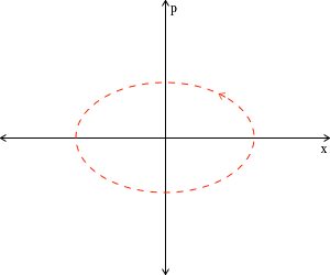
For an oscillating system, like a swinging pendulum, the map traces out a loop, like the above ellipse. It is curious but wonderful that the area inside the ellipse is measured in , the units of angular momentum. In the next chapter, we will discuss oscillations and phase mappings, thereby getting right up to the doorway into quantum physics.
- F.K. Mueller, “A History of Inertial Guidance,” Army Ballistic Missile Agency, Redstone Arsenal, Alabama, 1959. ↵